# Welcome
We're excited to have you here! This documentation is your gateway to understanding and leveraging the full power of **FPT AI Factory** — a comprehensive cloud platform designed to accelerate your AI development and deployment.
Whether you're building machine learning models, running inference jobs, or managing high-performance infrastructure, AI Factory provides everything you need.
### Jump right in
Cover image
FPT GPU CLOUD
Deploy GPU virtual machines, containers, and high-speed file storage.
# Starter Plan
# Terms & Conditions
## 1. Program overview
The Starter Plan is a one-time promotional offer available to new users of FPT AI Factory.
To verify their account, eligible users are required to make a $5 top-up. The $5 top-up amount will remain in the user's account balance.
After successful verification, users will receive $100 in promotional credits, resulting in a total account balance of $105.
The $100 promotional credits are valid for 30 days starting from the date they are received. Any unused promotional credits will expire after this period.
## 2. Eligibility
To qualify for the Starter Plan, you must meet **all** of the following conditions:
* Never registered an account on FPT AI Factory, **or** registered but have not yet generated any billable usage, made any top-up transaction, or claimed any promotion or voucher (excluding the $1 MODAS voucher, provided it has not been used)
* Each user may claim the Starter Plan **once only**. The offer is non-transferable. If you do not qualify, the system will display a notification explaining your ineligibility and no credit will be granted.
## 3. Verification & activation
* To activate the Starter Plan, you must add a valid payment method and complete a **$5 account verification charge**.
* The $5 charge will be added to your account balance. Upon successful verification, you will also receive **$100 in promotional credits** — bringing your total balance to **$105** ($5 top-up + $100 voucher).
* If you skip adding a payment method, you will **not** receive the $100 promotional credit.
## 4. Credit allocation
Your $100 in Starter Plan credits is allocated across services as follows:
| Service | Credit |
| ------------------- | -------- |
| GPU Virtual Machine | $15 |
| GPU Container | $15 |
| Token Factory | $70 |
| **Total** | **$100** |
{% hint style="warning" %}
Each service credit is fixed and cannot be shared or transferred to another service. If a service's credit is exhausted while a job is running, that job will be terminated. Monitor your balance before launching long-running workloads.
{% endhint %}
## 5. Credit terms
* Promotional credits are valid for **30 days** from the date of activation. Any unused balance will be forfeited upon expiry.
* Credits are **non-transferable**, **non-refundable**, and cannot be exchanged for cash.
* Credits cannot be used to pay for services outside the allocated categories.
* Once the credit balance allocated to a specific service reaches $0, that service will be paused and can only be resumed after you top up your account. Other services with remaining credit balances will continue to operate normally.
## 6. Fraud & misuse
* Creation of duplicate accounts to claim multiple Starter Plans is prohibited.
* Any abuse of this offer — including fraudulent account creation, system exploitation, or use of false payment information — will result in **permanent account suspension** and forfeiture of all credits.
## 7. General
* FPT AI Factory reserves the right to modify, suspend, or terminate the Starter Plan at any time without prior notice
* This offer applies to the Vietnam site ([https://ai.fptcloud.com](https://ai.fptcloud.com/)) only, not available on the Japan site ()
* For questions, contact FPT AI Factory support via the Help & Support section on the platform.
# Online Referral
**The Referral feature** is a mutual reward system. Invite friends via your unique link to **earn a $25 credit**, while your friends **receive a 30% bonus on their top-ups (upto $150) for the first 30 days.**
**1. How to use your link**
* Navigate to the **Referral** page on your dashboard.
* Click **Copy** to share your unique link with friends.
* Once your friend signs up and makes a qualifying first top-up (e.g., minimum $25), both of you will receive the bonus automatically!
**2. Dashboard metrics explained** Track your referral performance in the **Summary** section:
* **Total registered users:** The number of friends who successfully created an account using your link.
* **Referral credits:** The total bonus amount ($) you have earned from your friends' successful top-ups.
# Terms & Conditions General
**1. Rewards:**
**Referrer:**
* Earn a **$25 Bonus Credit** for every friend who signs up using your referral link and makes their first-time top-up of at least $25 **within 30 days of registration**.
* No earning limits.
{% hint style="warning" %}
No bonus will be awarded to the Referrer if the Referee **does not make a qualifying top-up within 30 days of registration**
{% endhint %}
**Referee:**
* Get a **30% Bonus Credit** on all qualifying top-ups (minimum $25 per top-up) made within the **first 30 days of registration.**
* Maximum bonus: **$150**.
* Top-ups below the minimum amount ($25) are not eligible for the bonus.
{% hint style="warning" %}
No bonus will be applied to top-ups made after the 30-day window.
{% endhint %}
{% hint style="success" %}
**How to earn more bonus?**
* Once registered, a Referee can also become a Referrer by sharing their own Referral URL (see the [Referral page](https://ai.fptcloud.com/AIMKP-MINHNN110-ZXTQK/referral) for your link).
* There's no limit to how many friends you can refer — keep sharing and keep earning!
{% endhint %}
**General:**
* Rewards are **promo credits only**. They are non-transferable, non-refundable, and expire **90 days from the issue date**.
***
**2. Eligibility:**
* The Referee must be a brand-new user to FPT AI Factory — never registered to FPT AI Factory before.
***
**3. Fraud & Penalties:**
* **No Self-Referrals:** If the Referrer and Referee use the same payment method, both rewards are automatically rejected.
* Spamming, fake accounts, or system exploitation will result in permanent account suspension.
***
**4. Program Changes:**
* FPT AI Factory reserves the right to modify or terminate this program at any time without prior notice.
# Terms & Conditions FPT Exclusive
**1. Rewards:**
**Referrer:**
* Open only to users with a registered account email ending in @fpt.com
* Earn a **$50 Bonus Credit** for every friend who signs up using your referral link and makes their first-time top-up of at least $50 **within 30 days of registration**.
* No earning limits.
{% hint style="warning" %}
No bonus will be awarded to the Referrer if the Referee **does not make a qualifying top-up within 30 days of registration**
{% endhint %}
**Referee:**
* Get a **30% Bonus Credit** on all qualifying top-ups (minimum $25 per top-up) made within the **first 30 days of registration.**
* Maximum bonus: **$150**.
* Top-ups below the minimum amount ($25) are not eligible for the bonus.
{% hint style="warning" %}
No bonus will be applied to top-ups made after the 30-day window.
{% endhint %}
{% hint style="success" %}
**How to earn more bonus?**
* Once registered, a Referee can also become a Referrer by sharing their own Referral URL (see the [Referral page](https://ai.fptcloud.com/AIMKP-MINHNN110-ZXTQK/referral) for your link).
* There's no limit to how many friends you can refer — keep sharing and keep earning!
{% endhint %}
**General:**
* Rewards are **promo credits only**. They are non-transferable, non-refundable, and expire **90 days from the issue date**.
***
**2. Eligibility:**
* The Referee must be a brand-new user to FPT AI Factory — never registered to FPT AI Factory before.
***
**3. Fraud & Penalties:**
* **No Self-Referrals:** If the Referrer and Referee use the same payment method, both rewards are automatically rejected.
* Spamming, fake accounts, or system exploitation will result in permanent account suspension.
***
**4. Program Changes:**
* FPT AI Factory reserves the right to modify or terminate this program at any time without prior notice.
# Metal Cloud
Metal Cloud enables you to deploy and manage bare metal servers globally. Our platform offers the flexibility of virtualized cloud environments with the performance, security, and control of dedicated
## **What is Metal Cloud?**
Metal Cloud is a form of cloud service in which the user rents a physical server with a built-in GPU component from FPT. This server is dedicated to the user and not shared with any other tenants.\
You can get access to servers with full control over their hardware without virtualization or abstraction layers, enabling maximum performance for compute-intensive workloads.\
\
*The server is also called a Bare Metal GPU server.*
## **How does it work?**
When you rent a Bare Metal GPU server, we allocate the entire physical machine exclusively for you, set up a physical networking configuration. You have 100% access to the computing and networking power of the machine because the server environment is fully isolated.\
\
You can configure the networking (subnet/IP), SSH key, user data, and install the operating system on the FPT Customer portal to deploy your server.
## **Why Metal Cloud?**
* Dedicated hardware for maximum performance
* High resource availability and scalability
* Advanced customization
* Improved performance and security
* Predictable costs
# Quickstart
Bare Metal GPUs servers are dedicated, single-tenant servers with 8 GPUs that can operate standalone or in multi-node clusters.
**Supported GPUs by Region**\
**Hanoi 2 (Vietnam)**: NVIDIA H100 SXM, NVIDIA B300\
**Tokyo (Japan)**: NVIDIA H200 SXM
### Sign Up for an Account
1. Access and choose **Sign up**.
2. Please check your **Junk** email folder if you don't see the confirmation email in your **Inbox**.
3. Sign in to [**https://console.fptcloud.com/**](https://console.fptcloud.com/) **in Vietnam region and** [**https://console.fptcloud.jp/**](https://console.fptcloud.com/) **in Japan region** to start using the service.
### Create a Subnet
A subnet is required to create and deploy your Bare Metal GPU server.
1. Click on **AI Infrastructure** and select **Subnet** in the Sidemenu.
2. Follow the detailed guide [here](https://fptcloud.com/en/documents/metal-cloud/?doc=subnet).
### Create Bare Metal GPU Servers
1. Click on **AI Infrastructure** and select **Metal Cloud** in the Sidemenu.
2. Choose **Create server** and configure the server deployment.
3. Two (02) FPT images for GPU and AI/ML are available; check the software dependencies [here](https://fptcloud.com/en/documents/metal-cloud/?doc=os-image).
4. You may select a **Floating IP (Public IP)** while creating the server to access it via the internet, or attach it later in the **Network/Floating IP**.
5. Follow the detailed guide [here](https://fptcloud.com/en/documents/metal-cloud/?doc=create-server).
### Access to Servers
1. **Attach a Floating IP** if you have not chosen it while creating servers with this [guide](/fpt-gpu-cloud/metal-cloud/tutorials/server-action)**.**
2. Configure **Network ACL** [here](https://fptcloud.com/en/documents/metal-cloud/?doc=network-acl) to create an inbound rule that allows your Public IPs.
3. SSH into the server with your SSH key or password as configured during creation.
4. You can also set a **Jump host** for additional security settings. Follow the guide [here](https://fptcloud.com/en/documents/metal-cloud/?doc=access-server).
\*The default username is **`clouduser` .**
### Notices
* Please check the **Tenant & Region** after accessing the FPT Cloud Console. AI Factory is only supported in the **Hanoi 2** (Vietnam) and **Tokyo** (Japan) regions.
* You may change the default **Network ACL**, but ensure to set up other required rules for creating servers.\
Here is the default outbound rule for a Network ACL, which you can delete.
| Priority | Type | Protocol | Port | Destination | Traffic Action |
| -------- | ---- | -------- | ---- | ----------- | -------------- |
| 100 | ALL | ALL | ALL | 0.0.0.0/0 | ALLOW |
If you delete the above default rule, you need to add the following outbound rules to create and deploy the server:
| Priority | Type | Protocol | Port | Source | Traffic Action |
| -------- | --------- | -------- | ---- | --------- | -------------- |
| 1 | HTTP | TCP | 80 | 0.0.0.0/0 | ALLOW |
| 2 | HTTPS | TCP | 443 | 0.0.0.0/0 | ALLOW |
| 3 | DNS (UDP) | UDP | 53 | 0.0.0.0/0 | ALLOW |
* FPT sets the **limitation (quota) for resource** quantity according to your contracts/agreements. If you run out of resources, you cannot create new ones. Please contact your salesman or reach out to [FPT Smart Cloud Support](https://support.fptcloud.com/en/support/tickets/new).
# Tutorials
# Subnet
A subnet is a range of IP addresses in a cloud network. Addresses from this range will be assigned to one or multiple servers in the Metal Cloud. Only IPv4 is supported.
#### Create a subnet
|
A CIDR range is allocated automatically. It will be held for 60 seconds and be updated to the new one after that on the screen.
A network ACL is required to create with a subnet. By default, only outbound traffic from the Bare Metal GPU server to the internet will be allowed.
The quota of subnet is equal to the quota of the Bare Metal GPU server.
|
| ------------------------------------------------------------------------------------------------------------------------------------------------------------------------------------------------------------------------------------------------------------------------------------------------------------------------------------------------------------------------------------------------------------------------------------------------- |

1. Sign in to your FPT Cloud account, select a **Tenant**, a **Region** and a **VPC.** (If you have more than one of them.)
2. Navigate to **AI Infrastructure** and **Subnet for Metal Cloud** in the sidebar, then click **Create subnet**
3. Enter a **Subnet name**
4. Enter a **Network ACL name**
5. Enter the **Network ACL description** (Optional)
6. Click **Create** **Subnet**
#### Delete a subnet
| You cannot delete a subnet that is associated with other resources. |
| ------------------------------------------------------------------- |
1. Navigate to **AI Infrastructure** and **Subnet for Metal Cloud**
2. in the sidebar to view the Server list
3. Choose a subnet and click **Actions**
4. Click **Delete**
5. Confirm the deletion by typing **DELETE** text
#### Update a subnet name
| A subnet name **can be duplicated** with existing names. |
| -------------------------------------------------------- |
1. Choose a subnet and click **Actions**
2. Click **Rename**
3. Enter the new subnet name that complies with the rule: Name limits up to 32 characters, and only letters, numbers, and dashes are allowed
4. Click **Rename subnet**
#### Update a subnet description
1. Choose a subnet and click **Actions**
2. Click **Update description**
3. Enter the new description. The length must be less than or equal to 63 characters long
4. Click **Save**
# Network ACL
#### Network ACL Overview
Network ACL (Access Control List) or NACL is a crucial part of network security. It helps control and manage traffic flow in and out of subnets by applying rules that either allow or deny access.
* A network ACL is automatically created with a subnet.
* Each subnet must be associated with a NACL.
* NACLs contain inbound and outbound rules. Priority values are evaluated in ascending order, and once a match is found, further rules are not evaluated.
* **Each NACL has a maximum limit of 100 rules (both inbound & outbound rules).**
#### A Network ACL rule consists of the following basic components:
You can modify the default network ACL by adding or removing rules. Any changes made to the rules of a network ACL are automatically applied to the associated subnets.
The components of a network ACL rule include:
| **Priority** |
Rules are processed in ascending order by priority number.
Once a rule matches the traffic, it is applied, even if higher-numbered priority rules conflict with it The system automatically increments the priority number, but the user can change it as long as it does not duplicate an existing number.
|
| ------------------ | ------------------------------------------------------------------------------------------------------------------------------------------------------------------------------------------------------------------------------------------------------------------------------------------------------------------------------------------ |
| **Type** | Specifies the type of traffic, such as HTTP, HTTPS, or ALL. |
| **Protocol** | NACL supports TCP, UDP, ICMP, or any protocols. |
| **Port** | The specific port of the traffic is targeted **from 1 to 65535.** |
| **Source** | For inbound rules, this specifies the origin of the traffic (CIDR range) |
| **Destination** | For outbound rules, this specifies the target of the traffic (CIDR range) |
| **Traffic action** | The specified traffic is permitted with **Allow** or\*\* Deny\*\* |
**Notices**
* The default rule is automatically created with a NACL that allows all outbound traffic, and you can delete it.
| Priority | Type | Protocol | Port | Source | Traffic Action |
| -------- | ---- | -------- | ---- | --------- | -------------- |
| 100 | ALL | ALL | ALL | 0.0.0.0/0 | ALLOW |
* If you delete the above default rule, you need to add the following outbound rules to create and deploy the server:
| Priority | Type | Protocol | Port | Source | Traffic Action |
| -------- | --------- | -------- | ---- | --------- | -------------- |
| 1 | HTTP | TCP | 80 | 0.0.0.0/0 | ALLOW |
| 2 | HTTPS | TCP | 443 | 0.0.0.0/0 | ALLOW |
| 3 | DNS (UDP) | UDP | 53 | 0.0.0.0/0 | ALLOW |
#### What you can do with a Network ACL

**Create new rules**
Creating an additional Network ACL allows (ALLOW) or denies (DENY) all or specific types of inbound and outbound traffic.

To create one or more Network ACL rules, follow these steps:
1. Sign in to your FPT Cloud account, select a **Tenant**, a **Region** and a **VPC;** (If you have more than one of them)
2. Navigate to **AI Infrastructure**/**Network ACL** in the sidebar;
3. Choose a network ACL by clicking a **NACL name** or **Actions/Manage rules** in the list;
4. Choose an **Outbound or Inbound Tab**; (if user want to create the corresponding traffic rule)
5. Click the button **Create new rule;**
6. Enter the Priority, Type, Protocol, Port, Source/Destination, and Traffic Action fields;
7. You can create multiple new rules and choose **Apply** to save changes.
**Modify existing rules**
To modify one or more Network ACL rules, follow these steps:
* Choose a network ACL by clicking a **NACL name** or **Actions/Manage rules** in the list;
* Click on the **Edit** icon in the rule you want to modify;
* Change the rule value to your desire;
* You can repeat and modify multiple existing rules and choose **Apply** to save changes.
**Remove rules**
To remove one or more Network ACL rules, follow these steps:
* Choose a network ACL by clicking a **NACL name** or **Actions/Manage rules** in the list;
* Click on the **Delete** icon in the rule you want to remove;
* You can repeat and delete multiple existing rules and choose **Apply** to save changes.
# OS Images
### FPT Images
FPT Image is a custom image built by FPT that you can use to get started quickly with any of the GPU servers available. This image comes with several components needed for AI workloads and selects Ubuntu as the Operating System (OS).
The versions of the installed dependencies are optimized for compatibility and might not be the latest versions available.
| | Ubuntu 22.04 GPU | Ubuntu 24.04 GPU | Ubuntu 26.04 GPU |
| --------------------------------------- | --------------------------------------------------------------------------------------------------------- | -------------------------------------------------------------------------------------------------------- | --------------------------------------------------------------------------------------------------------------------- |
| OS Base | Ubuntu 22.04 LTS (**Jammy Jellyfish**) | Ubuntu 24.04 LTS (**Noble Numbat**) | Ubuntu 26.04 LTS (**Resolute Raccoon**) |
| NVIDIA Driver | 580.159.04 | 580.159.04 | 610.57.04 |
| NVIDIA CUDA Toolkit | 13.0 | 13.0 | 13.3 |
| NVIDIA Fabric Manager (NVSwitch Driver) | 580.159.04 | 580.159.04 | 610.57.04 |
| NVIDIA DOCA OFED (Mellanox IB Driver) | 3.3.0-088000 | 3.3.0-088000 | 3.4.0-085000 |
| NVIDIA Datacenter GPU Manager | 4.5.3-1 | 4.5.3-1 | 4.6.1-1 |
| NVIDIA HPCX | v2.26-cuda13 | v2.26-cuda13 | **NOT YET** |
| High-performance storage client |
Vietnam region: VAST Data Client 4.0.40
Japan region: DDN Storage Client 2.14.0
|
Vietnam region: VAST Data Client 4.5.7
Japan region: DDN Storage Client 2.14.0
|
Vietnam region: VAST Data Client 4.5.8
Japan region: DDN Storage Client (Not supported yet)
|
| Python | 3.10.12 | 3.12.3 | 3.14.4 |
| Docker | 29.5.2-1 | 29.5.2-1 | 29.7.2-1 |
| NVIDIA Container Toolkit | 1.19.1-1 | 1.19.1-1 | 1.20.0-1 |
### Custom images
With custom image templates, you can capture an image of a Bare Metal GPU server to replicate its configuration with minimal changes in the order process. Image templates provide an imaging option for all Bare Metal GPU servers, regardless of operating system. When your image template is complete, you can use it to create another Bare Metal GPU server.
#### Upload an image
1. Sign in to your FPT Cloud account, select a **Tenant**, a **Region** and a **VPC.** (If you have more than one of them.)
2. Navigate to **AI Infrastructure** and **Custom images** in the sidebar, then click **Upload image.**\

3. To upload a file, click on the browser to **choose a file from your computer**, or **drag and drop your file.**\

4. Enter the **image name**
5. Click **Upload image**
| You cannot create a new server with this image until the imaging process is complete. The image template processing time varies based on the resources that are available on the physical host and how much data is being captured in the image template. |
| --------------------------------------------------------------------------------------------------------------------------------------------------------------------------------------------------------------------------------------------------------- |
Resume processing
You may resume the file processing if it fails.
1. In the Custom image list, Click **Actions** for the custom image with **Failed** status
2. Choose **Resume**
#### Delete an image
1. In the Custom image list, Click **Actions** for the custom image you want to delete, then choose **Delete**\

2. A confirmation window titled **Delete custom image** item opens. Click **Delete image** to confirm the deletion
| The server you’ve created from a custom image is not deleted when you delete the image from your account. You can destroy the Bare Metal GPU server from the FPT Customer portal separately. |
| -------------------------------------------------------------------------------------------------------------------------------------------------------------------------------------------- |
# RAID
### RAID Definition
A Redundant Array of Independent Disks (RAID) is a method of configuring member drives to create high availability and high performance systems. The RAID level provides different degrees of redundancy and performance; it also determines the number of members in the array
### RAID level
The RAID level is what determines the relationship of the disks.
| Level | Description | Drive count | Approximate array capacity | Redundancy\* |
| ------ | ------------------------------------------------------------------------------------------------------------------------------------------------------------------------------------------------------------------------- | ----------- | -------------------------- | ------------ |
| RAID 0 |
RAID 0 combines two or more disks by stripping data across them.
That chunks of data are written to each disk in the array alternately.
RAID 1 is a configuration that mirrors data between two or more disks.
Everything written to the array is placed on each of the devices in the group, so each disk has a complete set of the available data.
| 2 | Drive size | 1 |
\*Redundancy means how many drive failures the array can tolerate. In some circumstances, an array can tolerate more than 1 drive failure.
# User data
User data or Cloud-init automatically configures Bare Metal GPU servers after bootup. These scripts are generally used for the initial configuration of a server and run on the first boot.
Deploying a server with user data allows you to run arbitrary commands and change several aspects of the server during provisioning.
Here are a few examples of what you can do with user data scripts:
#### Creating a user and installing basic packages
| #cloud-config users: - name: cloud\_user ssh\_authorized\_keys: - ssh-rsa AAAAB3Nz... user\@domain sudo: "ALL=(ALL) NOPASSWD:ALL" groups: sudo shell: /bin/bash packages: - git - htop |
| -------------------------------------------------------------------------------------------------------------------------------------------------------------------------------------- |
What this script does:
1. Creates a user named cloud\_user.
2. Adds an SSH key to allow secure remote login.
3. Installs packages like git (a version control tool) and htop (a system monitor).
How you can test it:
To login, you’ll want to use a command of this form:
| ssh -i /.ssh/id\_rsa maas\_user\@10.192.226.195 |
| ----------------------------------------------- |
You can then test it further by running htop and trying out some git commands.
#### Setting up SSH keys for multiple users
| #cloud-config users: - **default** - name: user1 ssh\_authorized\_keys: - ssh-rsa AAAAB3Nz... user1\@domain - name: user2 ssh\_authorized\_keys: - ssh-rsa AAAAB3Nz... user2\@domain |
| ------------------------------------------------------------------------------------------------------------------------------------------------------------------------------------ |
What this script does:
1. Sets up a default user.
2. Creates user1 and user2 with their own SSH keys for secure login.
#### Installing Docker
| #cloud-config packages: - docker.io runcmd: - systemctl enable docker - systemctl start docker |
| ---------------------------------------------------------------------------------------------- |
What this script does:
1. Installs Docker on the machine.
2. Enables and starts Docker to make sure it’s running whenever the machine boots up.
# Create servers
You can deploy a bare metal server via the FPT Customer Portal. FPT takes care of provisioning, OS installation, and configuration based on the settings you choose. Once deployment is complete, you can access your server via SSH with an SSH key or password.
1. Sign in to your FPT Cloud account, select a **Tenant**, a **Region** and a **VPC.** (If you have more than one of them.)
2. Navigate to **AI Infrastructure** and **Metal Cloud** in the sidebar, then click **Create server**.
3. Select a **Flavor** (Its availability varies by region).
4. Enter the **number of servers** you desire to deploy at once. (The maximum number varies by your quota.)
5. Enter your **server names**
6. Select the **Operating System**\
If we don't offer the OS you're looking for, you can use a custom image instead.
7. Choose an available **Subnet**\
You cannot deploy a server without a subnet. Please create one before creating and deploying a server.
8. Choose to attach a **Floating IP (Optional)**
9. For Authentication, you can choose SSH key or Console password:
Choose an available **SSH key** or add a new one (Learn more about creating and adding your SSH keys here.)
10. Configure **RAID (Optional)**
11. Select or create a **User Data** script **(Optional)**\
User data scripts run automatically on the server’s first boot through the cloud-init process.
12. Click **Create server**
# Server actions
### Attach a Floating IP
1. Navigate to **AI Infrastructure** and **Metal Cloud** in the sidebar to view the Server list
2. Choose a server and click the **Actions** icon > **Attach Floating IP**
3. Select **Bare metal GPU server** option tại **Resources**
4. Select an available (reserved) IP, or choose **Allocate new from pool** to request a new IP (if your quota allows).\

### Power on & Power off a server
1. Navigate to **AI Infrastructure** and **Metal Cloud** in the sidebar to view the Server list
2. Choose a server and click **Actions**
3. Click **Power off** for a **Running** server or **Power off** for a **Stopped** server
4. Confirm your power off or power on action
### Delete a server
| Deleting a server permanently erases all data on its disks and **cannot be undone**. Ensure you are deleting the correct server. |
| -------------------------------------------------------------------------------------------------------------------------------- |
1. Navigate to **AI Infrastructure** and **Metal Cloud** in the sidebar to view the Server list
2. Choose a server and click **Actions**
3. Click **Delete**
4. Confirm the deletion by typing **DELETE** text
### Update name
| A server name is **unique** and **cannot be duplicated** with existing names. |
| ----------------------------------------------------------------------------- |
1. Navigate to **AI Infrastructure** and **Metal Cloud** in the sidebar to view the Server list
2. Choose a server and click **Actions**
3. Click **Rename**
4. Enter the new server name that complies with the rule: Name limits up to 63 characters, and only letters, numbers, and dashes are allowed
5. Click **Rename server**
# Access server
You can connect to the Bare Metal GPU server using SSH keys or a password.
The SSH protocol (also referred to as Secure Shell) is a method for secure remote login from one server to another. To connect via SSH, make sure that all the necessary rules for incoming traffic are in the Network ACL settings set.
### Console KVM
1. Navigate to **AI Infrastructure** and **Metal Cloud** in the sidebar to view the Server list
2. Choose a server in the list or view the details of a server
3. Click \*\*Actions,\*\*then **Console,or Click Open** at Console item in the Sever details page
4. Use the \*\*default username:\*\*clouduser and your password, which you entered when creating the server to log in.
### SSH
| The SSH key is selected when you create and deploy servers. Please refer to [SSH key management](https://fptcloud.com/documents/cloud-server/?doc=profile-ssh-key). |
| ------------------------------------------------------------------------------------------------------------------------------------------------------------------- |
#### Prerequisites before connecting from Windows 10
1. Open **Windows Settings**.
2. Go to the **Apps & features** section and click **Optional features**.
3. Find **OpenSSH Client** and click to expand the detailed description.
4. Click **Install**.
5. Wait for the installation to be completed. After SSH Client is installed, restart your computer to apply the settings correctly. SSH utility will become available for cmd.
#### Connect from Windows 10, Linux OS, macOS
1. Open the command prompt.
| Authentication methods | Command |
| ---------------------- | -------------------------------------------------------------- |
| A password | ssh username\@192.168.1.92 |
| SSH keys | ssh username\@192.168.1.92 -i "C:\Users\username\\.ssh\id\_rsa |
In there:
* * Replace "username" with your username or the \*\*default username (clouduser)\*\*for the first login
* Replace "192.168.1.92 with the Floating IP address of your server
* Replace "C:\Users\username.ssh\id\_rsa" with the path to your private key file in PEM format on your computer.
| If you created a Bare Metal GPU server with only a private interface, create a floating IP address and use it when connecting to the Bare Metal over ssh. |
| --------------------------------------------------------------------------------------------------------------------------------------------------------- |
1. The utility will warn you that you're trying to connect to an unknown device and ask if you want to continue. Type "**yes**" and press **Enter**.\
2. (Step for connecting using a password only) enter the password you configured while creating the Bare Metal.
### Use a Bastion host (jump server)
A jump host is an intermediate server between an originating machine and the Bare Metal GPU server you’re trying to connect to. It acts like a gate between two trusted networks: You can access a destination server, but only after the jump host has allowed access.
1. Create a Cloud instance with a subnet and a floating IP
2. Configure Security groups

# Monitoring
**The monitoring feature is bundled with AI Infrastructure – Metal Cloud service.**
Collecting and visualizing metrics, logs, and events can help identify potential issues and optimize future workloads. You may select an observability solution that best fits their needs.


| **Metrics** | **A Cluster (in the same VPC)** | **A single Server** |
| ------------------------------------------------------------------------------------ | ------------------------------- | ------------------- |
| Total number of nodes and down nodes | ✔ | |
| GPU model, Driver & CUDA version | | ✔ |
| Power state | ✔ | |
| Uptime | | ✔ |
| Total number of GPUs and down GPUs | ✔ | ✔ |
| GPU Utilization | ✔ | ✔ |
| GPU Memory | ✔ | ✔ |
| CPU Utilization | ✔ | ✔ |
| System Memory | ✔ | ✔ |
| Root Storage Usage | ✔ | ✔ |
| Local Disk Usage | ✔ | ✔ |
| **Details of each GPUs** Power consumption, Temperature, GPU Utilization, VRAM usage | | ✔ |
| Network Bandwidth Inbound/ Outbound | ✔ | ✔ |
| Network Packets Sent/Received | ✔ | ✔ |
| Network Error rate Receive/Transmit | | ✔ |
| Network InfiniBand Bandwidth/Packet/Error | | ✔ |
| System Fan Speed | | ✔ |
| System Voltage | | ✔ |
| Common Alerts | ✔ | |
*\*For custom or advanced metrics as requested, we offer a Cloud Monitoring (FMON) service available for an additional charge.*
# FAQ
**General**
1. **What is Metal Cloud?**\
Metal Cloud is a cloud service that provides dedicated physical servers with built-in GPU components from FPT. Unlike traditional cloud services, these servers are entirely dedicated to you, offering full control over the hardware without any virtualization layers. This ensures maximum performance for compute-intensive tasks.
2. **How does Metal Cloud differ from Cloud server (Virtual Machine) instances?**\
Unlike cloud server instances, which are virtualized and shared with other users, Metal Cloud gives you direct access to dedicated physical servers. This eliminates the risk of "noisy neighbors" and provides better performance for resource-intensive workloads like AI/ML and high-performance computing.
3. **How does Metal Cloud work?**\
Metal Cloud provides you with a physical, dedicated server that includes GPU components. This setup is ideal for high-demand applications such as AI/ML model training, custom orchestration, or any workload requiring stable and high-performance infrastructure.
4. **How long does it take to deploy a Bare Metal GPU server?**\
A Bare Metal GPU server can be deployed in approximately 20 minutes using FPT images. However, deployment time may vary depending on the size of custom images or if there is high server demand.
5. **What advanced use cases does Metal Cloud support?**
* **AI/ML Workloads:** Model training, fine-tuning, and inference for large-scale data.
* **Custom Orchestrations:** Containerized environments using Kubernetes, workload management with Slurm, and other complex application setups.
* **High-Performance Computing:** Ideal for simulations, scientific computations, and real-time data processing.
***
**Features**
6. **Which features does Metal Cloud currently support?**
* **Operating System Images:** FPT-provided AI-specific images.
* **Startup Scripts:** Automate initial configurations.
* **SSH Key Preloading & Password Setup:** Simplify access and security.
* **Networking:** Includes additional IPs, subnets, and network ACLs for security.\
**More features are coming soon, so stay tuned!**
7. **What storage options are available for Metal Cloud?**
* **NVMe Local Storage:** Available on Bare Metal GPU servers.
* **File Storage (High-Performance Tier):** Supported.\
Note: Block Storage service is not supported.
8. **Does Bare Metal Cloud support RAID?**\
Yes, the local storage supports RAID 0 and RAID 1 via a hardware RAID controller through the FPT Cloud Portal GUI. RAID 5 is available upon request from FPT engineers.
9. **Where is Metal Cloud available?**\
Metal Cloud is currently available in:
* **Hanoi 2, Vietnam**
* **Tokyo, Japan**
***
**Billing**
10. **How is Metal Cloud billed?**\
Metal Cloud uses a reservation-based pricing model. You pay a fixed price for a set amount of resources, which can be billed upfront (partially or fully) or on a recurring basis. Billing periods typically range from months to years.
# GPU Cluster
# Managed K8s with Metal Cloud
## Overview
**Managed GPU Cluster (Kubernetes)**
**FPT Managed GPU Cluster**is based on the open-source K8s platform, helping to automate the deployment, scaling, and management of containerized applications. FPT Managed GPU Cluster fully integrates the following components: Container Orchestration, Storage, Networking, Security, and PaaS, providing customers with the best environment for developing and deploying applications on the Cloud.
**FPT Managed GPU Cluster** is a Managed GPU Cluster service model provided by FKE. With MANAGED GPU CLUSTER, FPT Cloud manages all control-plane components, while users deploy and manage Worker Nodes. MANAGED GPU CLUSTER allows users to focus on application deployment without having to spend resources on managing K8s Clusters.
**FPT Managed GPU Cluster**is a service model based on the open-source Kubernetes platform, helping to automate the deployment, scaling, and management of containerized applications. The FPT Managed GPU Cluster product not only fully integrates components such as Container Orchestration, Storage, Networking, Security, and PaaS, but also provides GPU resources to support complex computing operations.
What should you consider before using **Managed GPU Cluster**?
* **Location of the Managed GPU Cluster**: The geographic location (Region) may affect the access speed to the server during use. You should choose the Region closest to the traffic source to optimize speed.
* **Number of Nodes and configuration of each Node to use**: All FPT Cloud accounts are allocated a certain quota for resources such as RAM, CPU, Storage, IP, etc. Therefore, customers should determine the amount of resources needed and the maximum limits to be met so that FPT Cloud can best support you.
If this is your first time using MANAGED GPU CLUSTER, first check and complete the following tasks:
# Initial Setup
### 1. Register a new account
Then select the **Sign Up** and enter the information according to the system instructions. The support team will contact you shortly thereafter to confirm the information and create your account.
To log in to the FPT Portal, please visit [console.fptcloud.com](https://console.fptcloud.com/) or [console.fptcloud.jp](https://console.fptcloud.com/).
After logging in with your assigned account and password, select the correct Tenant, Region, and VPC.
If you are unsure about the above information or the system returns an error after 3 attempts, please contact our Support team immediately for assistance.
**Note**: Your account must have two-factor authentication (MFA) enabled to use the AI Factory product.
### 2. Create Subnets for Bare Metal GPU Servers used in Managed GPU Clusters
To create a Managed GPU Cluster, you first need a subnet range on Bare Metal GPU Servers. These computers will act as Worker nodes in the K8s Cluster. IPv4 addresses for the Worker Bare Metal GPUs will be dynamically assigned from this subnet.
**Step 1:** Go to \[AI Infrastructure] > select \[Subnets] > select \[Create Subnet]

**Step 2**: Enter the desired name for the subnet

**Step 3:** Enter a name for the Network ACL associated with the subnet
**Step 4**: Click \[Create Subnet] to complete the subnet creation process for Bare Metal GPU
**Note**: The Network ACL created by default for the subnet will block all inbound traffic and allow all outbound traffic. To use Load Balancer for Managed GPU Cluster, you need to open the appropriate Rules for the Load Balancer subnet range to allow connections.
### 3. Create Subnets for Load Balancer
Managed GPU Clusters only work with Subnets that have the Static Pool option enabled, so you need to create a Subnet with Static Pool following these instructions:
**Step 1:** In the **Network** section, select the **Subnets** tab

**Step 2**: Select **Create Subnet** on the **Subnets Management** page

**Step 3:** Enter the following information:
**Name:** Enter a memorable name for the Subnet
**CIDR**: Enter a valid CIDR
Check the **Advanced settings** option
**Static IP Pool**: Enter a valid IP range obtained from CIDR.
Select **Save** to create a new Subnet. The system will process and notify you of the result.

### 4. Request to activate the Managed GPU Cluster service and allocate resource quotas.
If this is your first time using FPT Cloud, some services may not yet be available for your account. Please contact our support team and provide information about the services and desired configuration. We will provide you with the necessary resources such as RAM, CPU, Storage, Public IP, etc., so you can start using the Managed GPU Cluster service.
Contact our support team via:
**Hotline**: 1900638399
**Email**:
**Note:** Certain mandatory conditions apply for this operation:
* Quota Metal Cloud (Bare Metal HPC) must meet the desired number of clusters. At least 01 BM server Network
* At least 01 Network for Load Balancer
# Tutorial
# Create a cluster
**Step 1**: On the **FPT Portal** menu, select **AI Infrastructure**> **Managed GPU Cluster**>Create a Managed GPU Cluster.

**Step 2**: Enter the information in the General Information tab of the Cluster, then click the **Next button**:

1. General Information:
* **Name**: Enter the Cluster name. Cluster names must be unique and follow the rules.
* **Network**: Select from the subnet range created for Bare Metal GPU Servers
* **Version**: Select the Kubernetes version compatible with the customer's current application.
2. Load Balancer Service:
* **Internal LB Subnet**: Configure the private IP range for the Load Balancer service type.
3. Nodes Credentials:
* **SSH Public Key**: SSH Key to SSH into the Cluster's Worker node
4. GPU Information:
The **GPU Information section** allows you to configure the GPU software to install for your Kubernetes cluster. This is necessary if the cluster has nodes that use GPUs to accelerate workloads such as AI/ML, HPC, etc.
* GPU Software: Select the type of GPU software to install for the cluster. Current options:
* GPU Operator: GPU Operator helps manage GPUs and NVIDIA drivers on Kubernetes.
* Network Operator: Supports installing GPU Direct RDMA for high-speed data transfer over the network.
**Step 3**: Enter the information in the Nodes Pool tab of the Cluster, then click the **Next** button: Important points to note when creating a MANAGED GPU CLUSTER:
* **Managed GPU Cluster** manages Worker nodes through Worker Groups, which are groups consisting of Worker nodes with identical configurations. Users can divide Worker Groups for appropriate applications. The system requires a minimum of one Worker Group (Base), which users cannot delete.
* In the Worker Group configuration section, users can assign labels to the desired Worker Group. This label will be applied to all Worker nodes belonging to the Worker Group. Users can add or remove labels, as well as edit the key/value of existing labels. These labels make it easy for users to deploy applications on separate Worker Groups as needed.

**Worker Group 1 (Base):**
* * **Group Name**: Name the Worker Group to distinguish it from other Worker Groups.
* **Runtime**: Select the container runtime; currently, the system only supports the Containerd container runtime.
* **Number of Servers**: The number of Metal Cloud Servers created to run Workers in the Cluster.
* **Flavor**: The flavor type of the Metal Cloud GPU server, default is H100.
* **Worker MIG Strategy:**
MIG = Multi-Instance GPU: Split a physical GPU (such as H100) into multiple smaller GPUs multiple applications/Pods to share.
* **None**: No GPU splitting - each Pod uses the entire physical GPU.
* **Single**: Each GPU is divided into smaller portions.
* MIG-single-7x1g.10gb: Divide the physical GPU into 7 instances of 1g.10gb
* MIG-single-4x1g.20gb: Split the physical GPU into 4 instances of 1g.20gb
* MIG-single-3x2g.2gb: Divides the physical GPU into 3 instances of 2g.20gb
* MIG-single-2x3g.40gb: Divides the physical GPU into 2 instances of 3g.40gb
* MIG-single-1x4g.40gb: Split the physical GPU into 1 instance of 4g.40gb
* MIG-single-1.7g.80gb: Split the physical GPU into 1 instance of 7g.80gb
→ If you do not need to split the GPU, select **None**.
* * **GPU Driver**: Allows the operating system to recognize and use the hardware GPU. (Example: NVIDIA Driver)
* **Pre-Install**: The NVIDIA driver has been **pre-installed** on the virtual machine by FPT Cloud.
* **Driver Version**: FPT Cloud supports driver version 550.90.07 - CUDA 12.4
* **Label**: Apply a label in Kubernetes to all workers in the worker group.
Users can add worker groups when creating a k8s cluster by clicking the **ADD WORKER GROUP** button.

Additionally, starting from Worker Group 2, users can configure taints for worker groups to schedule applications on worker nodes. Taints can also be easily added, removed, or edited.

**Note**: When configuring labels/taints for a worker group on Unify Portal, users will not be able to remove labels/taints for nodes in that worker group using kubectl (the system will automatically reapply labels/taints to nodes according to the configuration on Unify Portal). Therefore, it is necessary to remove the label/taint configuration on Unify Portal.
Learn more about Taints [here](http://kubernetes.io/docs/concepts/scheduling-eviction/taint-and-toleration/)
**Note**: When configuring labels/taints for a Worker Group on the Portal, users will not be able to remove labels/taints for nodes in that Worker Group using kubectl (the system will automatically reapply labels/taints to nodes based on the configuration on the Portal). Therefore, it is necessary to remove the label/taint configuration on the Portal.
**Step 4**: The **Advanced** section contains advanced settings

* **Pod Network**: The network used for Pods in the Cluster.
* **Service Network**: Network used for Services in the Cluster.
* **Network Node Prefix**: Maximum number of Pods per Managed GPU Node.
* **Max Pod per Node**: The CNI type installed for the Cluster, only supports Calico.
**Step 5:** The Review & Create screen will display the cluster information that the user has configured previously, and the system will automatically check whether the Bare Metal GPU server quota is sufficient to create the cluster.

After the system successfully checks the resources, click the Create a Managed GPU Cluster button
to proceed with creating the cluster.
You can view and manage the list of GPU Clusters you have created on the Managed GPU Cluster page.
Management page. To open the Management page, follow these steps:
On **the FPT Portal**, select **AI Infrastructure**> **Managed GPU Cluster** from the menu. The system will display a list of created Clusters with important information such as: **Name**, **Version**, **Worker Group**, **Status**, **Created At**, **Actions**.

# Access a cluster
**Step 1**: In the menu, select **Managed GPU Cluster**, and the system will display the **Managed GPU Management** page. Select the Cluster for which you want to view detailed information.

**Step 2**: The **Essential Properties** tab will display the Cluster's information.

1. **Cluster Information**: Basic information about the cluster includes:
* Cluster Name: The name assigned when the cluster was created
* Version: The version of the cluster
* Configuration: Allows you to download kube-config to communicate with the cluster
* Network: The subnet range selected when creating the cluster
* Status: The actual status of the cluster
* SSH public key: The public key information selected when creating the cluster
1. \*\*GPU Software List:\*\*Displays all GPU software installed on the cluster
2. **Load Balancer Service**: Information about the Internal LB Subnet entered
3. **API**: API URL leading to the cluster
**Step 3**: The **Node Pools** tab displays all Worker Groups belonging to the cluster and the configuration information for each Worker Group.

* **Name**: Worker Group name
* **Is Based**: Display (✅) if it is a Worker base, and (✘) if it is not a Worker Base
* **Flavor Type**: Displays the selected resource flavor
* **Number of Servers**: Number of metal cloud servers for the Worker
# Kubernetes Configuration
The Kube-config file is used to store connection information to the Kubernetes cluster, helping tools such as kubectl, kubelet, and kubeâdm determine how to communicate with the Kubernetes API Server. The kubeconfig file is very important in managing access to Kubernetes, so it must be carefully secured.
To download the Kube-config file, customers should follow these instructions:
**Step 1**: In the menu, select **AI Infrastructure**> **Managed GPU Cluster**. The system will display the **GPU Cluster Management** page. Select the cluster for which you want to retrieve cluster access information.

**Step 2**: Under **Essential Properties**> Cluster Information > Configuration, you can download
the kubeconfig file to log in to the Cluster via kubectl or other tools.
Note:
Managed GPU Cluster uses Native Kubernetes Cluster as its core, allowing users to use the Cluster with kubectl tools and dashboard just like a regular Kubernetes Cluster.
# GPU Software
**GPU Software**refers to **software that supports GPUs**so they can function properly in a container/Kubernetes environment.
FPT Cloud supports customers in installing GPU software right from the moment they create a cluster, or customers can install it on an existing cluster. To add GPU software, customers should follow these instructions:
In the menu, select **AI Infrastructure**> **Managed GPU Cluster**. The system will display the **GPU Cluster Management** page. Select the cluster to which you want to add GPU software.

**Step 2: On the Essential Properties tab, click the Addbutton.**

**Step 3:** Select the GPU Software to install on the cluster, then click the **Save** button.

The system will install the GPU operator on the cluster within a few minutes. After successful installation, the status will change to Ready.

When installing the GPU Operator on the cluster, the system will automatically set Worker MIG Strategy = None. Customers can change the Worker MIG Strategy and MIG Profile according to their usage needs.

# Deploy applications
**Step 1:** Check the GPU configuration using the following command:
kubectl get nodes -o json | jq '.items\[].metadata.labels'
Example: The image below shows a worker using Metal Cloud GPU H100, with the strategy configuration: all-disable, status: success.

**Step 2:** Check the GPU instance configuration on the worker by SSHing into the node and typing the following command:
Nvidia-smi
The example below shows that the GPU driver has been successfully installed and is running with 8 GPUs in None mode.

**👉 Example of deploying an application using the GPU:**
```
#Syntax:
nvidia.com/gpu:
#Example:
nvidia.com/gpu: 1
#Example deployment using GPU
apiVersion: apps/v1
kind: Deployment
metadata:
name: example-gpu-app
spec:
replicas: 1
selector:
matchLabels:
component: gpu-app
template:
metadata:
labels:
component: gpu-app
spec:
containers:
- name: gpu-container
securityContext:
capabilities:
add:
- SYS_ADMIN
resources:
limits:
nvidia.com/gpu: 1
image: nvidia/samples:dcgmproftester-2.0.10-cuda11.0-ubuntu18.04
command: ["/bin/sh", "-c"]
args:
- while true; do /usr/bin/dcgmproftester11 --no-dcgm-validation -t 1004 -d 300; sleep 30;
```
# GPU Sharing
Note: Before changing the Worker MIG Strategy, scale the application using GPU Operator to 0
**Step 1:** In the menu, select **AI Infrastructure**> **Managed GPU Cluster**. The system will display the **GPU Cluster Management** page. Select the cluster you want to add GPU software to.

**Step 2:** In the Node Pools tab, select the Worker MIG Strategy you want to use.

**Step 3**: Select the MIG Profile, then click the Save button

**None**: No GPU sharing - each Pod uses an entire physical GPU.
**Single**: Each GPU is divided into smaller portions.
* MIG-single-7x1g.10gb: Divides the physical GPU into 7 1g.10gb instances
* MIG-single-4x1g.20gb: Divides the physical GPU into 4 instances of 1g.20gb
* MIG-single-3x2g.2gb: Split the physical GPU into 3 instances of 2g.20gb
* MIG-single-2x3g.40gb: Divides the physical GPU into 2 instances of 3g.40gb
* MIG-single-1x4g.40gb: Split the physical GPU into 1 instance of 4g.40gb
* MIG-single-1.7g.80gb: Split the physical GPU into 1 instance of 7g.80gb
→ If you do not need to split the GPU, select **None**.
Note:
The MIG strategy change process will take a few minutes, and the Cluster status will change to **Processing** until the new worker successfully joins the cluster. The cluster will continue to operate normally during this process
# Cluster Manual-Scaling
Manual Scale allows users to actively adjust the scale of system resources as needed. Users can increase or decrease the number of Metal Cloud Servers per day on the portal by following these steps:
**Step 1**: In the menu, select **AI Infrastructure**> **Managed GPU Cluster.**The system will display the
**Managed GPU Management**. Select the cluster to which you want to add a Worker Group.

**Step 2**: Click on the cluster you want to scale, then select **Node Pools**> **Edit Workers**.
 
**Step 3**: Update **the Number of Servers** to increase it according to your usage needs, then click the Save button.

Note:
The manual server scaling process will take a few minutes. The Cluster status will change to **Processing** until the new worker successfully joins the cluster. The cluster continues to operate normally while scaling new servers.
Labels and Taints are two important mechanisms that help manage and distribute workloads efficiently in systems with multiple Worker Groups, making it easy to group workers by purpose, performance, or geographic region. Managed GPU Cluster allows users to add, edit, or delete labels/taints directly on the Unify Portal.
**Step 1**: In the menu, select **AI Infrastructure**> **Managed GPU Cluster**. The system will display the Managed GPU Cluster Management page. Select the cluster you want to edit the Label/Taint for.

**Step 2**: Select **Node Pools**> **Edit Workers**

**Step 3**: Enter the Labels and Taints you want to add to the Worker Group and click the **Save** button
Notes:
* The process of editing Labels and Taints will take a few minutes, and the Cluster status will change to **Processing**. While this is happening, users cannot edit the Cluster until the process is complete.
* When users wish to change the base Worker Group, system components (coredns, metrics servers, CNI controller, etc.) will be redeployed on the Worker nodes belonging to the new base Worker Group. This feature is beneficial when users want to increase/decrease the flavor configuration of Worker nodes in the base Worker Group. In this case, users create a new Worker Group with the desired Worker node configuration, make the new Worker Group the base, and delete the old base Worker Group.
**Step 1**: In the menu, select **AI Infrastructure**> **Managed GPU Cluster**. The system will display the Managed GPU Cluster Management page. Select the cluster for which you want to change the Worker Group configuration.

**Step 2**: Select **Node Pools**> **Edit Workers**.

**Step 3**: Select the Worker Group you want to change and click the **Save** button.

Note:
* The process of changing the Worker Group Base will be performed, and during this process, users cannot edit the Cluster until the process is complete.
* When changing the parameters of the Worker Group, the system will first create new Worker nodes with the desired configuration. Once the new Worker nodes are successfully created, the Worker node with the old configuration will be removed from the system. The pods will be transferred from the old Worker node to the new Worker nodes.
# Add a Worker group
Managed GPU Cluster allows users to add worker groups to the cluster as needed. To add workers, customers can perform the following steps on the portal:
**Step 1**: In the menu, select **AI Infrastructure**> **Managed GPU Cluster**. The system will display the
**Managed GPU Management**. Select the cluster to which you want to add a Worker Group.

**Step 2**: Select **Node Pools**> **Edit Workers**.

**Step 3**: Select **Add Worker Group**.

**Step 4**: Enter the required information fields and click **Save**.

* **Group Name**: Name the Worker Group to distinguish it from other Worker Groups
* **Container Runtime**: Select the container runtime; currently, the system only supports the Containerd container runtime
* **Flavor**: Resource flavor of the Worker GPU
* **Number of Servers**: Number of Metal Cloud Servers created to run Workers in the Cluster
* **Label**: Apply a label to the Worker Group
* **Taint**: Apply a taint to the Worker Group
**Note**: The process of adding a new Cluster will take a few minutes, and the Cluster status will change to **Processing**. The Cluster will continue to operate normally while adding a new Worker Group.
# Delete a cluster
For Managed GPU Clusters that are no longer needed, customers can delete them by following
the following instructions:
**Step 1**: In the menu, select **AI Infrastructure**> **Managed GPU Cluster**. The system will display the **GPU Cluster Management** page. Select the Cluster you want to retrieve information about to access the Cluster.

**Step 2**: Select **Action**at the end of the Cluster you want to delete from the list. Select Delete.

**Step 3**: Confirm the warning information in the popup and select **Delete**.

# Cluster configuration
The Managed GPU Cluster product is developed from Kubernetes Native and integrates additional cloud provider components into Kubernetes, including the FPT Cloud Controller Manager component. This component aims to manage worker nodes in the cluster and Load Balancer-type services. Users can expose their applications to the internet in many ways so that their customers can access the applications and services. These methods may include creating an ingress for the service, creating a node port service and attaching a floating IP to the worker node, or using a Load Balancer service.
FPTCloud supports users in creating load balancer services with accompanying annotation options
in the service configuration:
| | | | |
| ----------------------------------------------------- | -------------- | ----------- | ------------------------------------------------------------------------------------------------------------------------------------------------------- |
| **Key** | **Value** | **Default** | **Purpose** |
| service.beta.kubernetes.io/fpt-load-balancer-internal | "true"/"false" | "false" | If you do not want to expose the service to the internet, set the value to "true" |
| loadbalancer.fptcloud.com/keep-floatingip | "true"/"false" | "false" | If you want to keep the LoadBalancer service's floating IP within the VPC after deleting the service, set the value to "true" |
| loadbalancer.fptcloud.com/proxy-protocol | "true"/"false" | "false" | If you want the LoadBalancer to use the PROXY protocol, configure the value as "true". Note: The Proxy protocol is only used with Layer 4 LoadBalancers |
| loadbalancer.fptcloud.com/enable-health-monitor | "true"/"false" | "true" | To disable the health monitor for the LoadBalancer Pool, set the value to "false". |
| | | | |
| ------------------------------------------------- | ------------------------------------------------------------------------------------------------------------- | ----------------------------- | ----------------------------------------------------------------------------------------------------------------------------------------------------------------------------------------------------------- |
| service.beta.kubernetes.io/fpt-load-balancer-type | LBv1 includes: basic/ advanced/ standard/ premium LBv2 includes: Basic-1/ Basic-2/ Standard/ Advanced/Premium | LBv1: "basic" LBv2: "Basic-1" | Configure the LoadBalancer flavor to handle the corresponding load of the application behind the LoadBalancer pool backend |
| loadbalancer.fptcloud.com/enable-ingress-hostname | "true"/"false" | "false" | To enable ingress hostname for the LoadBalancer service type, set the value to "true" |
| loadbalancer.fptcloud.com/load-balancer-version | "v1"/"v2" | "v1" | To use LBv2 for the LoadBalancer service type, configure the value as "v2". LBv1 will be created by default if not configured this annotation |
| loadbalancer.fptcloud.com/x-forwarded-for | "true"/"false" | "false" | To forward the request header to the LoadBalancer pool backend when using LoadBalancer layer7, configure the value as "true". Note: You cannot use the proxy protocol and x-forwarded-for at the same time. |
Additionally, Managed GPU Cluster supports users to configure:
**Create a LoadBalancer service type specifying a floating IP attached to the Load Balancer**
Note: The public IP must be allocated to the VPC and be in the Inactive state. The user goes to the
**Networking -> Floating IPs** to check.
**Restrict access to the Load Balancer by configuring**
**\_"loadBalancerSourceRanges"\_in the \_"spec"\_section of the service configuration:**

* 14.233.234.0/24
* 10.250.0.0/24
Note: The "loadBalancerSourceRanges" configuration contains an array of public IP ranges allowed to access the Load Balancer. By default, M-FKE creates a Load Balancer service type with the source IP range configured as 0.0.0.0/0.
Ollama is an open-source tool that allows you to run, manage, and customize large language models (LLMs) on personal computers or servers, supporting various models such as Llama, DeepSeek, Mistral, etc. Open-WebUI is an open-source web interface specifically designed to
interact with Ollama, providing a user-friendly experience and making it easy to manage and use LLM models.
This document will guide you through the steps to deploy the DeepSeek-R1 model on the FPT Managed GPU Cluster using Ollama and Open-WebUI so that users can use it simply and easily.
**Step 1**: Clone the existing source code and script of Open-WebUI

git clone
**Step 2**: Run the scripts to deploy ollama and open-webui. The directory contains all the files needed for deployment, such as **namespace**, **ollama statefulSet**, **ollama service**, **open-webui deployment**, and **open-webui service**.

kubectl apply -f ./kubernetes/manifest
**Step 3**: Access open-webui in your browser at the forwarded port, for example: [*http://localhost:52433*.](http://localhost:52433/) For the first time installing and using OpenWebUI, users will need to configure the following information: name, email, password.

**Step 4**: After installation is complete, the user selects the model to use. For example, here we will install the DeepSeek-R1 model, version\*\* 1.5b\*\*.

**Step 5**: After the model has been loaded and run, users can interact with the model very simply
and intuitively through the interface.

# Using with High-performance Storage
## Requirements
* Required conditions for creating a Managed GPU cluster (Active service, metal cloud quota, SSH key, internal subnet LB, etc.).
* Ensure that the File Storage – High Performance service is enabled and has been allocated a quota within the tenant.
* To use a Mount Point belonging to the Metal cloud network, navigate to the File Storage – High Performance tab to create a new Mount Point following the instructions [here](https://ai-docs.fptcloud.com/ai-infastructure/high-performance-storage)
## Enable the File Storage – High Performance
### Integrate with a new Managed GPU cluster:
**Step 1:** On the FPT Cloud Portal menu, select AI Infrastructure → Managed GPU Cluster → Create a Managed GPU Cluster.

* Select the correct network of the Metal Cloud server as the worker node in the GPU cluster, and the mountpoints of File Storage – High Performance will be displayed depending on this network.
**Step 2**: Once you have the MountPoint in the desired metal cloud network, enable File Storage – High Performance and select the desired MountPoint.
Note: If the tenant has not activated the File Storage – High Performance service, the following message will appear. You must submit a request to activate the service before performing integration on the Managed GPU Cluster.
 
**Step 4:** Review all High Performance Storage Integration information and proceed to create the Managed GPU Cluster.
### Integrate with an existing Managed GPU cluster


**Step 1:** On the FPT Portal menu, select AI Infrastructure → Managed GPU Cluster → select an existing cluster to integrate File Storage – High Performance
Note: The Managed GPU cluster integrated with File Storage – High Performance must be in the Succeeded (Running) state before integration can be performed.

**Step 2**: In the Essential Properties tab → High Performance Storage Integration, click Enable High Performance Storage → select MountPoint from the list, then click the "Confirm" button.

The High Performance Storage integration process will take a few minutes, and the Cluster status will change to **Processing until** the integration is successful. The Cluster will continue to operate normally during the integration.

## Remove File Storage – High Performance integration
* Only remove the File Storage – High Performance integration when the cluster status is **Succeeded (Running).** Before removing the integration, delete all PVCs in the cluster using the selected mountpoint. Canceling the integration does not automatically delete data written by Kubernetes in the MountPoint directory.
* Step 1: On the FPT Portal menu, select AI Infrastructure → Managed GPU Cluster → select the cluster that has integrated File Storage – High Performance
* Step 2: In the Essential Properties tab → High Performance Storage Integration → disintegrate → Confirm

## Modify Mount Point

At any given time, only one MountPoint can be used on a Managed GPU cluster. To change the MountPoint used in the cluster, you must first unmount the old MountPoint (Section 2.3) and then mount the new MountPoint for the cluster (Section 2.2).
## Using the Mount Point in Cluster
**Managed GPU cluster:** After successful integration, the cluster will have a storageclass available to create Persistence Volumes (PVs) located in the directory assigned to the MountPoint path. The name of the storageclass is the name of the integrated MountPoint QoS Policy.
For example, if the MountPoint path is /k8s-cluster1, PVs created by CSI in Kubernetes will have paths such as /k8s-cluster1/PV1, /k8s-cluster1/PV2, etc.

* Create a PersistentVolumeClaim (PVC) using the system's existing storageclass for the integrated MountPoint. Since the storageclass's VOLUMEBINDINGMODE is WaitForFirstConsumer, a Pod must use this PVC for CSI to create the PV and bind it to the PVC.
* Note: Do not modify the cluster's default storageclass configuration. If the user changes that configuration, it will automatically roll back to the system's original configuration.
* Example manifest of a PVC:
```
apiVersion: v1
kind: PersistentVolumeClaim
metadata:
name: csi-pvc-dynamic-1
namespace: default
spec:
accessModes:
- ReadWriteMany
resources:
requests:
storage: 15Gi
storageClassName: k8s-tester
volumeMode: Filesystem
```
* To resize the PVC capacity, directly edit the PVC resource in the `spec.resources.requests.storage` field.
* Note: Capacity cannot be reduced (only increased). If PVC is being used by a Pod, the system will automatically resize the capacity of the mountPath in the Pod (resize volume online).
# Use cases
# Serving DeepSeek-R1
Using Ollama and Open WebUI
Ollama is an open-source tool that enables running, managing, and customizing large language models (LLMs) on personal computers or servers, supporting various models such as Llama, DeepSeek, Mistral, and more. Open-WebUI is an open-source web interface specifically designed to
Interact with Ollama, providing a user-friendly experience for managing and using LLM models.
This document will guide you through the steps to deploy the DeepSeek-R1 model on the FPT Managed GPU Cluster using Ollama and Open-WebUI so that users can use it simply and easily.
**Step 1**: Clone the existing Open-WebUI source code and script
```
git clone https://github.com/open-webui/open-webui
cd open-webui/kubernetes
```
**Step 2**: Run the scripts to deploy ollama and open-webui. The directory contains all the necessary files for deployment, such as **namespace**, **ollama statefulSet**, **ollama service**, **open-webui deployment**and **open-webui service**.
```
cd kubernetes
kubectl apply -f ./kubernetes/manifest
```
**Step 3**: Access open-webui on the browser at the forwarded port, for example: [*http://localhost:52433*](http://localhost:52433/). For the first time installing and using OpenWebUI, users will need to configure the following information: name, email, password.
**Step 4**: After installation is complete, users select the model to use. For example, here we will install the DeepSeek-R1 model, version **1.5b**.

**Step 5**: Once the model has been loaded and run, users can interact with the model very simply and intuitively through the interface.


# Slurm on Managed GPU Cluster
The Managed GPU Cluster is built on the open-source K8s platform, automates the deployment, scaling, and management of containerized applications. It fully integrates components such as Container Orchestration, Storage, Networking, Security, and PaaS, providing customers with an optimal environment for developing and deploying applications on the Cloud.
FPT Cloud manages all control-plane components, while users deploy and manage the Worker Nodes. This allows users to focus on deploying applications without spending resources on managing the Kubernetes Cluster.
Based on the open-source Kubernetes platform, Managed GPU Cluster automates the deployment, scaling, and management of containerized applications. In addition to full integration of Container Orchestration, Storage, Networking, Security, and PaaS components, it also provides GPU resources to support complex computing tasks.
Things to note before using the Managed GPU Cluster
* Cluster location: The geographic region can affect access speed during usage. You should select the Region closest to the traffic source to optimize performance.
* Number of Nodes and their configurations: Every account is assigned certain quotas for resources like RAM, GPU, CPU, Storage, IPs, etc. Therefore, customers should determine the number of resources needed and the maximum limits required so FPT Cloud can provide the best support.
## Overview
Slurm is a powerful open-source platform used for cluster resource management and job scheduling. It is designed to optimize performance and efficiency for supercomputers and large computer clusters. Its core components work together to ensure high performance and flexibility. The diagram below illustrates how Slurm operates.

* slurmctld:\
The controller daemon of Slurm. Considered the “brain” of the system, it monitors cluster resources, schedules jobs, and manages cluster states. For higher reliability, a secondary slurmctld can be configured to avoid service interruption if the primary controller fails, ensuring high availability.
* slurmd:\
The node daemon of Slurm. Deployed on every compute node, it receives commands from slurmctld and manages job execution, including job launching, reporting job status, and preparing for upcoming jobs. slurmd communicates directly with compute resources and forms the basis of job scheduling.
* slurmdbd:\
The database daemon of Slurm. Although optional, it is crucial for long-term management and auditing in large clusters, as it maintains a centralized database for job history and accounting information. It can aggregate data from multiple Slurm-managed clusters, simplifying and improving data management efficiency.
Slurm CLI: provides commands to manage jobs and monitor the system:
* scontrol: manage the cluster and control cluster configurations
* squeue: query job status in the queue
* srun: submit and manage jobs
* sbatch: submit batch jobs for scheduled and resource-managed execution
* sinfo: query overall cluster status, including node availability
## Why Slurm on K8s?
Both Slurm and Kubernetes can serve as workload management systems for distributed model training and HPC (High-Performance Computing) in general.
Each system has its own strengths and weaknesses, with significant trade-offs. Slurm provides advanced scheduling, efficiency, fine-grained hardware control, and accounting capabilities, but lacks general-purpose flexibility. Conversely, Kubernetes can be used for many workloads beyond training (e.g., inferencing) and offers excellent auto-scaling and self-healing.
Unfortunately, there is currently no straightforward way to combine the benefits of both systems. And because many large tech companies use Kubernetes as the default infrastructure layer without support for specialized training systems, some ML engineers simply do not have a choice.
Using Slurm on Kubernetes allows us to leverage Kubernetes’ auto-scaling and self-healing capabilities within Slurm, while introducing unique features—all while retaining the familiar interaction model of the Slurm ecosystem.
## Slurm on Managed GPU Cluster
The Slurm Operator uses the custom resource SlurmCluster (CR) to define the configuration files required for managing Slurm clusters and solving issues related to control-plane management. This helps simplify the deployment and maintenance of clusters managed by Slurm. The figure below illustrates the architecture of Slurm on the FPTCloud Managed GPU/K8s cluster. A cluster administrator can deploy and manage a Slurm cluster through SlurmCluster. The Slurm Operator will create the control components of Slurm inside the cluster based on SlurmCluster. A Slurm configuration file may be mounted into the control component through a shared volume or a ConfigMap.
In the Slurm-on-K8s deployment model, the components of a Slurm cluster such as login nodes, worker nodes, etc are represented as pods on Kubernetes. At the same time, in this model, the concept of a shared-root volume is implemented, simply understood as deploying a shared filesystem—this filesystem is equivalent to the filesystem of an OS. Every job, after being sent to a worker node, will be executed inside this shared-root environment.
This ensures that every worker node always has identical configurations, packages, and state without manual management. In other words, when you install packages on one node, those packages automatically appear on the remaining nodes.
All you need to do is define your desired Slurm cluster in the Slurm cluster custom resource. The Slurm Operator will perform the deployment and management of the Slurm cluster for you according to the state you defined in the Slurm cluster CR.
### Deploy a Slurm Cluster on K8s
#### **Requirements**
* The K8s cluster must support dynamic provisioning volume and still have available storage quota.
* At least one StorageClass must be able to provide ReadWriteMany volumes.
#### **Step-by-Step**
**Step 1:** Install the Slurm Operator, GPU Operator, and Network Operator in the GPU software installation section and wait until all of them reach the ready state.
**Step 2:** In the K8s cluster, pre-create the Persistent Volumes to store the shared root space and controller node data.
Pay attention to the volumes in the Slurm-on-K8s deployment model:
Where:
* `jail-pvc`: mounted into worker nodes and login nodes, serves as a shared sandbox, the environment where jobs are executed, and also where users operate. The size of this volume must be at least 40Gi to store the filesystem of an OS.
* `controller-spool-pvc`: Stores cluster configuration data and is mounted on the controller node.
jail-pvc.yaml
```
apiVersion: v1
kind: PersistentVolumeClaim
metadata:
name: jail-pvc
namespace: fpt-hpc
spec:
storageClassName: default
accessModes:
- ReadWriteMany
resources:
requests:
storage: 100Gi
```
controller-spool-pvc.yaml
```
apiVersion: v1
kind: PersistentVolumeClaim
metadata:
name: controller-spool-pvc
namespace: fpt-hpc
spec:
storageClassName: default
accessModes:
- ReadWriteMany
resources:
requests:
storage: 10Gi
```
Notes:
* These volumes are all mandatory. They must provide ReadWriteMany and the PVC names must remain exactly as above.
* For convenience in deployment, we have used dynamic provisioning volume on the FPTCloud Managed K8s product.
* For production environments, we recommend mounting the root volume from a static partition belonging to a file server, to facilitate migration and maintenance of the Slurm cluster.
**Step 3:** Download the SlurmCluster Helm chart and configure parameters
```
helm repo add xplat-fke https://registry.fke.fptcloud.com/chartrepo/xplat-fke
helm repo update
helm repo list
helm search repo slurm
helm pull xplat-fke/helm-slurm-cluster --version 1.14.10 --untar=true
```
**Note**: Adjust the slurm-cluster version to match the version of Slurm Operator.
To learn more about the parameters of a Slurm cluster, we recommend you to read section 4: Parameters in the Slurm cluster
```
cd helm-slurm-cluster/
vi values.yaml
```
In the values.yaml file of the downloaded folder, you need to adjust several important fields such as:
After configuring the cluster as needed, run:
```
helm install fpt-hpc ./ -n fpt-hpc
```
**Step 4:** Wait until all Slurm pods are in the running state
This process takes around 20 minutes when installing a Slurm cluster for the first time on a K8s cluster. It includes 2 phases: phase 1 runs setup jobs, and phase 2 installs Slurm components.
When all components are ready, find the login node’s public IP using:
```
kubectl get svc -n fpt-hpc | grep login
```
SSH into the Slurm cluster head node:
```
ssh root@
```
If using nodeshell:
```
chroot /mnt/jail
sudo -i
```
Run tests:
```
srun --nodes=2 --gres=gpu:1 nvidia-smi -L
salloc --nodes=1 --ntasks=1 --mem=4G --time=00:20:00 --gres=gpu:1
```
### Run a Sample Job on the Slurm Cluster
After logging in successfully to the Slurm cluster, you can verify its operation by training the minGPT model following the steps below:
**Step 1:** Clone the pytorch/examples repository
```
mkdir /shared
cd /shared
git clone https://github.com/pytorch/examples
```
Step 2: Navigate to the minGPT-ddp folder & install the necessary packages
```
cd examples/distributed/minGPT-ddp
pip3 install -r requirements.txt
pip3 install numpy
```
Due to the shared-root mechanism, we only need to run this once; these packages will automatically sync to all remaining worker nodes.
**Note**: In production environments, we recommend using a conda environment/container to create a training environment instead of installing packages directly into the global environment.
**Step 3**: Edit the Slurm script
```
vi mingpt/slurm/sbatch_run.sh
```
**Note**: Adjust the path to the main.py file inside sbatch\_run.sh to the actual path in the mingpt folder.
**Step 4**: Run the sample Slurm job
```
sbatch mingpt/slurm/sbatch_run.sh
```
**Step 5**: Check status
```
squeue
scontrol show job <>
cat <>
```
## Parameters in the Slurm cluster
In section 3 of the guide for running Slurm on K8s, we guided you to adjust the most important parameters. In this section, we will go deeper into understanding the parameters/attributes defined for a Slurm cluster; you can also read the comments in the values.yaml file of the Slurm cluster custom resource downloaded in section 4 for additional information.
Attribute
Sample value
Description
clusterName
"fpt-hpc"
cluster name (note: do not change)
k8sNodeFilters
N/A
Divides the K8s cluster into two lists: GPU nodes (to deploy slurm workers) and non-GPU nodes to deploy other components. In case the cluster only has GPU nodes, these two lists can be the same.
volumeSources
volumeSources:
- name: controller-spool
persistentVolumeClaim:
claimName: "controller-spool-pvc"
readOnly: false
- name: jail
persistentVolumeClaim:
claimName: "jail-pvc"
readOnly: false
Defines the PersistentVolumeClaims used by the containers representing the components (worker, login, controller nodes, …) of the Slurm cluster.
periodicChecks
N/A
A periodic job to check the status of a node. If that node contains a GPU with issues, drain that node.
summonses
N/A
Defines the number and configuration of component nodes in a Slurm cluster (login node, worker node, …)
slurmNodes.accounting
enabled: true
mariadbOperator:
enabled: true
resources:
cpu: "1000m"
memory: "1Gi"
ephemeralStorage: "5Gi"
replicas: 1
replication: {}
storage:
ephemeral: false
volumeClaimTemplate:
accessModes:
- ReadWriteOnce
resources:
requests:
storage: 10Gi
storageClassName: xplat-nfs
Configuration of accounting node. Here we use the mariadb operator to create the database; you can also use an external database (read more in values.yaml).
slurmNodes.controller
size: 1
k8sNodeFilterName: "no-gpu"
slurmctld:
port: 6817
resources:
cpu: "1000m"
memory: "3Gi"
ephemeralStorage: "20Gi"
munge:
resources:
cpu: "1000m"
memory: "1Gi"
ephemeralStorage: "5Gi"
volumes:
spool:
volumeSourceName: "controller-spool"
jail:
volumeSourceName: "jail"
Configuration of the controller node, with 1 controller node + mounting 2 volumes (spool & jail shared root space) into this node.
slurmNodes.worker
size: 8
k8sNodeFilterName: "gpu"
cgroupVersion: v2
slurmd:
port: 6818
resources:
cpu: "110000m"
memory: "1220Gi"
ephemeralStorage: "55Gi"
gpu: 8
rdma: 1
munge:
resources:
cpu: "2000m"
memory: "4Gi"
ephemeralStorage: "5Gi"
volumes:
spool:
volumeClaimTemplateSpec:
storageClassName: "xplat-nfs"
accessModes: ["ReadWriteOnce"]
resources:
requests:
storage: "120Gi"
jail:
volumeSourceName: "jail"
Configuration of worker nodes, with 8 worker nodes, each node has 8 GPUs + mounts the jail (shared root space) volume into this node.
Configuration of login nodes, with 2 login nodes, exposing the sshd service using the load-balancer service type in K8s, using the public key defined in sshRootPublicKeys for the root user, and mounting the same volumes as the controller node & worker node.
slurmNodes.exporter
exporter:
enabled: true
size: 1
k8sNodeFilterName: "no-gpu"
exporter:
resources:
cpu: "250m"
memory: "256Mi"
ephemeralStorage: "500Mi"
munge:
resources:
cpu: "1000m"
memory: "1Gi"
ephemeralStorage: "5Gi"
volumes:
jail:
volumeSourceName: "jail"
Install the node exporter for monitoring.
For more detailed information, please read the comments in the values.yaml file defining the Slurm cluster configuration.
## Common use cases
### Add user/login
* Add users: To add an SSH key for root, you simply need to edit the Slurm cluster CR:
```
kubectl edit SlurmCluster fpt-hpc -n fpt-hpc
```
* In the login node configuration section, navigate to the sshRootPublicKeys attribute and add your desired public key.
* To add a regular user, you do the same as adding a user on a Linux host:
```
sudo adduser <>
```
* Modify login settings
By default, we expose the login node through a public Load Balancer. This may not be suitable for some requirements. Therefore, you can change the LB type to private, use the port-forward mechanism to access the Slurm cluster, or customize it according to your needs at our portal + LB node.
### Scale up/down worker nodes
To edit the number of worker nodes specifically and the number of other types of nodes in general, we simply need to edit the Slurm cluster CR:
```
kubectl edit SlurmCluster fpt-hpc -n fpt-hpc
```
In the worker nodes configuration section, navigate to the “size” field and edit the number of worker nodes as desired.
**Notes:**
* When scaling up the number of worker nodes, the new node will be automatically added to the list of worker nodes in the Slurm controller node and be ready to run jobs.
* When scaling down nodes, you need to manually delete the node on the Slurm controller using the command:
```
scontrol delete nodeName=<>
```
The node list in a cluster will always be: worker-\[0, (size - 1)].
### Migrate Slurm cluster to another K8s cluster
Thanks to the flexibility of K8s and network file storage, we can easily move a Slurm cluster from one K8s cluster to another. What needs to be done is mounting & recreating the jail-pvc on the new Slurm K8s cluster and performing the steps to create the Slurm K8s cluster again.
### Mounting external volumes into the Slurm cluster
To mount a volume into the Slurm cluster, you need to create that volume first, then deploy it as a PV & PVC on K8s. The following example uses dynamic provisioning to create this PV/PVC (in production environments, we recommend using static provisioning volumes to ensure data safety).
**Step 1**: Create PVC
```
apiVersion: v1
kind: PersistentVolumeClaim
metadata:
name: jail-submount-mlperf-sd-pvc
spec:
storageClassName: default
accessModes:
- ReadWriteMany
resources:
requests:
storage: 100Gi
```
**Step 2**: Declare this volume in the Slurm cluster
Edit the `volumeSource` field in the Slurm cluster CR:
```
kubectl edit SlurmCluster fpt-hpc -n fpt-hpc
```
```
volumeSources:
- name: controller-spool
persistentVolumeClaim:
claimName: "controller-spool-pvc"
readOnly: false
- name: jail
persistentVolumeClaim:
claimName: "jail-pvc"
readOnly: false
- name: mlperf-sd
persistentVolumeClaim:
claimName: "jail-submount-mlperf-sd-pvc"
readOnly: false
```
**Step 3**: Mount these volumes into the login and worker nodes in the Slurm cluster
In the login node:
```
volumes:
jail:
volumeSourceName: "jail"
jailSubMounts:
- name: "mlcommons-sd-bench-data"
mountPath: "/mnt/data-hps"
volumeSourceName: "mlperf-sd"
```
In the worker node:
```
volumes:
spool:
volumeClaimTemplateSpec:
storageClassName: "xplat-nfs"
accessModes: ["ReadWriteOnce"]
resources:
requests:
storage: "120Gi"
jail:
volumeSourceName: "jail"
jailSubMounts:
- name: "mlcommons-sd-bench-data"
mountPath: "/mnt/data-hps"
volumeSourceName: "mlperf-sd"
```
**Note**: The mount path must be the same across all worker nodes and login nodes.
# Managed K8s with GPU Virtual Machine
## Overview
FPT Cloud provides Kubernetes using NVIDIA GPUs with the following key features:
* Flexible GPU configuration with multiple GPU types, optional GPU memory, applied per Worker Group.
* Automated management and provisioning of GPU resources in Kubernetes with NVIDIA Operator.
Visualization and monitoring of GPUs using NVIDIA DCGM.
* Automatically scale containers/nodes with Autoscaler when application demand for GPU resources increases/decreases.
* Support GPU sharing with the Multi-Instance mechanism, helping to optimize GPU resource and cost usage.
FPT Cloud uses NVIDIA GPU Operator to provide tools for automatically managing all the software components needed to use GPUs on Kubernetes. GPU Operator allows users to use GPU resources just like they use CPUs in a Kubernetes cluster.
The Operator's components include:
* NVIDIA Drivers (CUDA, MIG, etc.)
* NVIDIA Device Plugin
* NVIDIA Container Toolkit
* NVIDIA GPU Feature Discovery
* NVIDIA Data Center GPU Manager (Monitoring)
In the Hanoi 2 and Japan regions, FPT Cloud currently supports Kubernetes using Nvidia H100 GPUs and Nvidia H200 GPUs
| **No.** | **GPU H100 SXM5** | **Strategy** | **Number instance** | **Instance resource** |
| ------- | ----------------- | ------------ | ------------------- | ------------------------------------ |
| 1 | all-1g.10gb | single | 7 | 1g.10gb |
| 2 | all-1g.20gb | single | 4 | 1g.20gb |
| 3 | all-2g.20gb | single | 3 | 2g.20gb |
| 4 | all-3g.40gb | single | 2 | 3g.40gb |
| 5 | all-4g.40gb | single | 1 | 4g.40gb |
| 6 | all-7g.80gb | single | 1 | 7g.80gb |
| 7 | all-balanced | mixed |
|
| 8 | none (no label) | none | 0 | 0 (Entire) |
***Example:***
* If you select the single strategy configuration: all-1g.10gb, the H100 GPU card on the worker is divided into 7 mig-devices with logical GPU resources (equal to 1/7 of the physical GPU) and 10GB of GPU RAM.
**Note:**
MIG configuration applies to all cards attached to the worker. The MIG strategy on worker groups within the same cluster must be the same type (single/mixed/none).
### Terminology and Definitions\[TP1]
Terminology
Definition
K8s
Kubernetes
FKE
FPT Kubernetes Engine
D-FKE
Dedicated – FPT Kubernetes Engine
M-FKE
Managed – FPT Kubernetes Engine
Master Node
Nodes containing control plane components
Worker nodes
Nodes used for executing workloads
Automatic scaling of nodes
Automatic scaling of worker nodes (increase/decrease)
K8S cluster
A collection of nodes (VMs) configured as a Kubernetes cluster.
NFS persistent storage
A "persistent" storage partition on NFS.
Pod
The smallest unit managed by Kubernetes. A Pod contains one or more containers.
Pod network
The network/subnet used to assign IP addresses to Pods.
Service Network
The network/subnet used to assign IP addresses to services.
# Initial Setup
If you are using M-FKE for the first time, please first verify and complete the following tasks.
* Create an FPT Cloud account and log in to the FPT Portal
* Create a subnet in Static Pool
* Request to enable the M-FKE service and allocate resource quotas
#### 1. Create an FPT Cloud account and log in to the FPT Portal
To register for an FPT Cloud account, visit the homepage.
After that, select the "Sign Up" feature and follow the system instructions to enter your information. The support department will contact you promptly to verify the information for account creation.
To log in to the FPT Portal, please access [https://console.fptcloud.com](https://console.fptcloud.com/)/.
After logging in with the provided account and password, correctly select the Tenant , Region, and VPC.
If you have any questions about the above information, or if the error persists after three attempts, please contact the support team.
#### 2. Creating a Subnet Using a Static Pool
Since **Kubernetes clusters** only operate on subnets with the **Static** Pool option enabled, you must create **a subnet using** Static **Pool** by following the steps below.
**Step 1**: Select the **\[Subnets]** tab under **\[Networking].**

**Step 2:** On the **\[Subnets Management]** page, select **\[Create].**

**Step 3:** Enter the following information.
* **Name:** Enter a **memorable name** for the subnet.
* **CIDR:** Enter a valid **CIDR.**
* Select the " " option. **Advanced Settings**
* **Static IP Pool:** Enter a valid IP range derived from the CIDR.
Select " ". Click **"Save"** to create the new subnet. The system will process the request and notify you of the result.
#### 3. Requesting FKE Service Activation and Resource Quota Allocation
If you are new to FPT Cloud, some services may not yet be available on your account. Please contact our support team and provide information about the desired services and settings. We will allocate the resources required to use the M-FKE service (RAM + CPU, storage, public IP, etc.).
# Tutorial
# Create a cluster
FPT Cloud supports the following cards:
* In the Hanoi 2 and Japan regions, the following GPU cards are supported: **H100 SXM5, H200 SXM5**
## Requirements
* CPU, GPU, RAM, Storage, and Instance quotas: Must be sufficient for the desired Kubernetes cluster configuration. If using Autoscale, the number of GPUs must meet the desired maximum node count (note the Min node and Max node settings).
* 01 Network subnet: Network used for Kubernetes Nodes, the subnet must have a Static IP Pool.
## Step-by-Step
### **GPU H100 SXM5**
**Step 1**: On the FPT Cloud Portal menu, select **Containers**> **Kubernetes**> **Create a Kubernetes Engine**.
**Step 2**: Enter the basic information for the cluster, then click the **Next** button:

#### Basic Information:
* Name: Enter the cluster name.

* **Net**work: Subnet used to deploy Kubernetes Cluster Virtual Machines (VMs).
* **Version**: Select the version of the Kubernetes Cluster.
* **Cluster Endpoint Access**: Select the Kubernetes cluster endpoint access option.
Step 3: Configure the Nodes Pool according to your needs, then click the **Next** button:
For the H100 card, the portal does not support creating GPU workers as the base worker group. Customers should create GPU workers starting from worker group 2 onwards.
#### Base worker group:
* Instance Type: Select the General Instance type
* Type: Select the configuration (CPU & Memory) for the **Worker Nodes**.
* Container Runtime: Select **Containerd**.
* Policy: Select the **Storage Policy** type (corresponding to IOPS) for the Worker Node Disk.
* Disk: Select the root disk capacity for the **Worker Nodes**.
* Scale min: Minimum number of Worker Node VM instances for the k8s cluster. The recommended minimum is 03 Nodes for the Production environment.
* Scale max: The maximum number of Worker Node VM instances for a worker group in the k8s cluster.
* Label: Apply a label to **the Worker Group.**
#### Worker Group n:
* Select instance type: GPU
* Select GPU type: NVIDIA H100 SXM5
* Select GPU sharing configuration
* Select GPU type configuration (CPU/RAM/GPU RAM)
**Note:**
1. In the "GPU Driver Installation Type" section, there are two options: **Pre-install**and **User-install**.
2. A driver is a program that allows the operating system to communicate with the hardware, specifically in this case between the worker's operating system (Windows, Ubuntu, etc.) and the GPU. The operating system cannot use the GPU without a driver.
3. For the "Pre-install" option, the customer's cluster will have the Nvidia GPU driver automatically added.
4. For the "User-install" option, customers can manually install the GPU driver to select the appropriate driver version.
**Step 4**: Click Create and review the initialization information.
**Step 5**: Monitor the Kubernetes cluster creation status. Once the status shows "Successed (Running)," proceed to use and deploy the application.
### **GPU H200 SXM5**
**Step 1**: On the FPT Portal menu, select **Containers**> **Kubernetes**> **Create a Kubernetes Engine**.
Step 2: Enter the basic information for the cluster, then click the **Next** button:

#### Basic Information:

* **Name**: Enter the Cluster name.
* **Network**: Subnet used to deploy Kubernetes Cluster Virtual Machines (VMs).
* **Version**: Select the version of the Kubernetes Cluster.
* **Cluster Endpoint Access**: Option to access the Kubernetes cluster endpoint.
#### Note:
* Customers need to select the appropriate Cluster Endpoint Access based on the security requirements and network architecture of the system.
* If Public & Private or Private is selected, an additional Allow CIDR field will appear to enter a list of IP address ranges that have access to the Kubernetes Cluster Endpoint.
**Step 3**: Configure the Nodes Pool according to your usage needs, then click the **Next** button:
For the GPU H200, the portal does not support creating GPU workers as worker group bases. Customers are kindly requested to create GPU workers starting from worker group 2 onwards.
#### Worker Group base:
* Instance Type: Select General Instance Type
* Type: Select the configuration (CPU & Memory) for the **Worker Nodes**.
* Container Runtime: Select **Containerd**.
* Policy: Select the **Storage Policy** type (corresponding to IOPS) for the Worker Node Disk.
* Disk: Select the root disk capacity for **Worker Nodes**.
* Scale min: Minimum number of Worker Node VM instances for the k8s cluster. The recommended minimum is 03 Nodes for the Production environment.
* Scale max: The maximum number of Worker Node VM instances for a worker group in the cluster.
#### Worker Group n:
* Label: Assign a label to **the Worker Group**
* Select instance type: GPU
* Select GPU type: NVIDIA H200 SXM5
* Select GPU sharing configuration
* Select GPU configuration type (CPU/RAM/GPU RAM)
**Note:**
1. In the "GPU Driver Installation Type" section, there are two options: **Pre-install** and **User-install**.
2. A driver is a program that allows the operating system to communicate with hardware, specifically in this case between the worker's operating system (Windows, Ubuntu, etc.) and the GPU. The operating system cannot use the GPU without a driver.
3. For the "Pre-install" option, the customer's cluster will have the Nvidia GPU driver automatically added.
4. For the "User-install" option, customers can manually install the GPU driver to choose the appropriate driver version.
**Step 4**: Click Create and review the initialization information.
**Step 5**: Monitor the Kubernetes cluster creation status. Once the status shows Successed (Running), proceed to use and deploy the application.
# Manage a cluster
## **View the list of clusters**
On the **Kubernetes Management** page, you can view and manage the list of existing Kubernetes clusters. To open **Kubernetes Management**, follow these steps:
In the **FPT Portal** menu, select **Kubernetes**. The system displays a list of existing clusters organized by **Name, Version, Worker Group, Type, Status, Creation Date, and Action.**
## **Accessing Cluster Details**
**Step 1:** Select **Kubernetes** from the menu to display the **Kubernetes Management** page. Select the cluster for which you want to view details.
**Step 2:** The cluster information is displayed on the **\[Essential Properties]** tab.
* **Cluster Information:** Basic cluster information includes the cluster name, Kubernetes version, Kubernetes configuration file, status, purpose of ~~the SSH key file~~, and auto-upgrade version (if enabled).
* **Load Balancer VIP**: Information about the selected load balancer size.
* **Worker Group Settings:** List of groups and settings Worker Nodes: Minimum/maximum count, CPU, memory, disk.
* **API:** API URL for the cluster.
**Step 3:** The **\[Node Pools]** tab displays all worker groups belonging to the cluster and the configuration information for each worker group.
* **Name:** Worker group name
* **Is Based:** Display (ü) if worker-based, (û) if not worker-based
* **Instance Type:** Display the instance type (CPU or GPU)
* **Resource Type:** Display the amount of CPU and RAM
* **Disk:** Display disk capacity
* **Policy:** Display information about the selected storage policy
* **Auto Scale:** Displays (ü) if auto scaling is enabled, (û) if disabled
* **Min Node:** Displays the minimum number of worker node VM instances configured for the worker group.
* **Max Node:** Displays the maximum number of worker node VM instances configured for the worker group.
* **Action:** Users can delete worker groups that are no longer in use. Note: Worker group bases cannot be deleted
## **Obtaining Cluster Access Information**
**Step 1:** Select **"Containers" > "Kubernetes"** from the menu to display the **Kubernetes Management** page. Select the cluster whose information you want to access.
**Step 2:** Under **Essential Properties > Cluster Information > Configuration,** download the kubeconfig file to log into the cluster using tools like kubectl.
***Tip:** M-FKE uses Native Kubernetes, allowing users to manage the cluster using kubectl and dashboard tools just like a standard Kubernetes cluster.*
## **Kubeconfig Rotation**
When using a Kubernetes cluster, you can perform a kubeconfig rotation. Example: When you need to change the certificate for user authentication
**Step 1:** Select **\[Containers] > \[Kubernetes]** from the menu to display the **Kubernetes Management** page.

**Step 2:** Select **\[Renew kubeconfig]** under **\[Configuration]** in the **\[Essential Properties]** tab.

**Step 3:** Review the warning information in the pop-up and click the **\[Renew]** button.

## **Deleting a Kubernetes Cluster**
Unneeded **Kubernetes clusters** can be deleted using the following steps.
**Step 1:** Select **\[Containers] > \[Kubernetes]** from the menu to display the **Kubernetes Management** page.
**Step 2**: From the list, select **\[Action]** at the end of the cluster you want to delete. Select **\[Delete]**.
**Step 3:** Review the warning information in the pop-up and select **"Delete".**
# Modify worker groups
## Requirements:
* CPU, GPU, RAM, Storage, Instance quotas: Must be sufficient for the Worker Group configuration changes.
* The number of GPUs must meet the Min node + 1 requirement so that Worker Nodes can roll out the configuration. If using Autoscale, the number of GPUs must meet the desired Max node requirement.
* 01 Network subnet: Network used for Kubernetes Nodes, the subnet must have a Static IP Pool.
## Step by Step
**Step 1**: Access the FPT Cloud portal [console.fptcloud.com](https://console.fptcloud.com/), select Kubernetes, click on the cluster you want to change, select Node Pools, and click the "Edit Workers" icon.

**Step 2**: In addition to the configuration information for the standard Worker Group, you need to select the configuration for the GPU:
Select instance type: GPU
Select GPU type (A30, A100, H100, H200, etc.)
Select the GPU sharing configuration (None/Single/Mixed) Select the GPU type configuration (CPU/RAM/GPU RAM)

**Note**:
* Changing the GPU sharing method will require all GPU-related workloads to be redeployed, so before making changes, users must scale the application down to 0 to avoid errors.
* If GPU sharing was previously set to None or None with Operator, you cannot change GPU sharing to Single or Mixed.
* If you previously selected Single for GPU sharing, you can only change it to the corresponding Single modes.
**Step 3**: Review the initialization information and click Save.
**Step 4**: Monitor the initialization status of adding the Worker Group to the Kubernetes cluster. Once the status shows Successed (Running), proceed to use and deploy the application.
# Modify cluster settings
## **1. Adding a Worker Group**
**Step 1**: Select **\[Containers] > \[Kubernetes]** from the menu to display the **Kubernetes Management** page. Select the cluster to which you want to add a worker group.
**Step 2:** Select **Node Pools > Edit Workers.**
**Step 3**: Select **ADD WORKER GROUP.**
**Step 4:** Enter the required information in each field.
* **Instance Type:** Select **the worker node instance type** (CPU or GPU).
* **Type:** Select **the worker node configuration** (CPU and memory).
* **Container Runtime:** Select **Containerd.**
* **Storage Policy:** Select the storage policy type for the worker node disk (supports IOPS).
* **Disk (GB):** Select the capacity **of the worker node's root disk.**
* **Network:** Select the subnet used to deploy Kubernetes cluster VMs.
* **Scale min**: Minimum number of VM instances for worker nodes in the k8s cluster. A minimum of 3 nodes is recommended for production environments.
* **Scale max**: The maximum number of VM instances for worker nodes in the worker group within the k8s cluster.
* **Label:** Apply a label to a **worker** group
* **Taint:** Apply a Taint **to the worker group.**
**Step 5**: Review the information and select **"Save"** to add the new worker.
Adding the cluster takes a few minutes, and the cluster status changes to "**Processing."** The cluster continues to function normally even after adding a new worker group.
## **2. Editing Worker Group Labels/Taints**
**Step 1:** Select **\[Containers] > \[Kubernetes]** from the menu to display the **Kubernetes Management** page. **Select the cluster** whose labels/taint you wish to edit.
**Step 2:** Select **Node Pools > Edit Workers.**
**Step 3:** Enter the labels and **taints** you want to add to the worker group, then click the **\[Save]** button.
*Note: Label and taint editing takes effect within a few minutes, and the cluster status changes to **"Processing."** Users cannot perform editing operations on the cluster until this process completes.*
## **3. Enabling/Disabling Automatic Node Repair**
**In addition to cluster autoscaling,** FPTCloud provides a node auto-healing feature that automatically restarts worker nodes that remain in the NotReady state for over 3 minutes. This feature is effective when worker nodes become overloaded or when issues related to the container runtime or kubelet cause a node to enter the NotReady state. If a node fails to return to the Ready state after auto-repair, the system replaces the NotReady node with a new node with identical settings after 10 minutes. This feature is enabled by default for worker groups (worker groups containing cluster system components). Users can enable or disable this feature for other worker groups within the cluster.
**Step 1:** Select **"Containers" > "Kubernetes"** from the menu to display the **Kubernetes Management** page. Select the cluster for which you want to enable/disable Node Auto-repair.
**Step 2:** Select **Node Pools** > **Edit Workers.**
**Step 3:** **Within ****worker**** pool, toggle the Node auto repair feature on or off.**
*Note: Only version upgrades are possible; downgrades cannot be performed.*
**Step 4:** Click the **\[Save]** button.
Editing the Node auto repair on/off setting takes effect within a few minutes, and the cluster status changes to **Processing.** During execution, you cannot perform any cluster editing operations until the process completes.
## **4. Worker Group-Based Migration Feature**
If a user wishes to change the worker group base, system components (such as CoreDNS, Metrics Server, CNI Controller, etc.) will be redeployed to worker nodes belonging to the new worker group base. This feature is useful when you want to increase or decrease the worker node flavor configuration within a worker group base. In such cases, create a new worker group with the desired worker node configuration, migrate to that new worker group base, and then delete the old worker group base.
**Step 1:** Select **\[Containers] > \[Kubernetes]** from the menu to display the **Kubernetes Management** page. Select the cluster for which you want to modify Worker Group settings.
**Step 2:** Select **Node Pools > Edit Workers.**
**Step 3:** Select the worker group you want to modify.
**Step 4:** Review the information and select **\[Save]** to save the changes.
The Worker Group Base modification process will run. While it is running, users cannot perform any editing operations on the cluster until the process completes.
***Tip:** When changing worker group parameters, the system first creates new worker nodes with the desired configuration. Once new worker nodes are successfully created, the old worker nodes are removed from the system. Pods are migrated from the old worker nodes to the new worker nodes.*
## **5. K8s Version Upgrade**
**Step 1:** Select **\[Containers] > \[Kubernetes]** from the menu to display the **Kubernetes Management** page. Select the cluster for which you want to upgrade the K8s version.
**Step 2:** Under **\[Cluster Information] > \[Version]**, select the **\[Setting]** icon.
**Step 3:** Select the version to upgrade to and choose **\[Upgrade].**
***Note:** Only version upgrades are possible; downgrades cannot be performed.*
*To avoid issues during processing, we recommend upgrading versions sequentially.*
## **6. Changing Cluster Endpoint Access**
### 1️⃣ **To change the access mode for a Kubernetes cluster**
⚠️ **Note**:
* M-FKE only supports converting access modes between Public & Private ➔ Private and vice versa.
* M-FKE does not support access mode conversion when the Kubernetes cluster is in Public mode.
**Step 1:** Select the cluster whose access mode you want to change and click its name.
**Step 2:** Under \[Cluster Endpoint Access], click the \[Edit] button.
**Step 3:** Select the desired access mode, enter a valid Allow CIDR, and click the Confirm button.
### 2️⃣ **To update the Allow CIDR:**
**Step 1:** Select the cluster whose access mode you want to change and click the cluster name.
**Step 2:** Under Cluster Endpoint Access, click the Edit button.
**Step 3:** Enter additional valid CIDR ranges and click the Confirm button.
### 2️⃣ **To remove an Allow CIDR:**
**Step 1**: Select the cluster whose access mode you want to change and click the cluster name.
**Step 2:** Under "Cluster Endpoint Access," click the Edit button.
**Step 3:** Delete all existing CIDRs and click the Confirm button.
⚠️ The access mode update will be applied within a few minutes, and the cluster status will change to **"Processing."** The cluster will continue to function normally during the transition to the new access mode.
## **7. Changing Internal Subnet Load Balancer (CIDR) Settings**
FPT Cloud supports customers who wish to change the range of their Internal Subnet Load Balancer (CIDR) on the Unify Portal. Customers should follow the steps below.
**Step 1**: Select the cluster for which you wish to change the Internal Subnet Load Balancer and click the cluster name.
**Step 2**: Select the \[Advanced] tab and click the \[Config Internal subnet Load Balancer] button.
**Step 3**: Enter a valid CIDR range and click the "Confirm" button.
⚠️ The internal subnet load balancer update will be performed within a few minutes, and the cluster status will change to "Processing." The cluster will continue to function normally during the transition to the new internal subnet load balancer (CIDR).
# Deploy applications
## Overview
Kubernetes manages and uses GPU resources in the same way as CPU resources. Depending on the GPU configuration selected for the Worker Group, declare GPU resources for the application on Kubernetes.
Note:
* You can specify GPU limits without specifying requests, as Kubernetes uses limits as the default request value.
* You can specify both GPU limits and requests, but these two values must be equal.
* You cannot specify GPU requests without specifying limits.
* Check the GPU configuration using the following command:
`kubectl get node -o json | jq ‘.items[].metadata.labels‘`
Example: The image below shows a worker using an Nvidia A30 card, configuration strategy: all-balanced, status: success.\

Check the GPU Instance configuration on the worker using the following command \
(SSH into the worker, type the command):
Example of deploying an application using GPU:
## **With the sharing mode MIG and Single strategy**
GPU resources are declared as follows:
```
nvidia.com/gpu:
#Example:
nvidia.com/gpu: 1
*(With the single strategy, the GPU card is divided into equal instances)
```
Example deployment using the single GPU strategy
```
apiVersion: apps/v1
kind: Deployment
metadata:
name: example-gpu-app
spec:
replicas: 1
selector:
matchLabels:
component: gpu-app
template:
metadata:
labels:
component: gpu-app
spec:
containers:
- name: gpu-container
securityContext:
capabilities:
add:
- SYS_ADMIN
resources:
limits:
nvidia.com/mig-1g.6gb: 1
image: nvidia/samples:dcgmproftester-2.0.10-cuda11.0-ubuntu18.04
command: ["/bin/sh", "-c"]
args:
- while true; do /usr/bin/dcgmproftester11 --no-dcgm-validation -t 1004 -d 300; sleep 30; done
```
## **With MIG and mixed sharing modes**
GPU resources are declared as follows:
```
nvidia.com/:
#Example
nvidia.com/mig-1g.6gb: 2
*(With the mixed strategy, a GPU card can be split into two instance types, so you must specify the instance type when declaring resources.)
```
Example deployment using the mixed GPU strategy
```
apiVersion: apps/v1
kind: Deployment
metadata:
name: example-gpu-app
spec:
replicas: 1
selector:
matchLabels:
component: gpu-app
template:
metadata:
labels:
component: gpu-app
spec:
containers:
- name: gpu-container
securityContext:
capabilities:
add:
- SYS_ADMIN
resources:
limits:
nvidia.com/mig-1g.6gb: 1
image: nvidia/samples:dcgmproftester-2.0.10-cuda11.0-ubuntu18.04
command: ["/bin/sh", "-c"]
args:
- while true; do /usr/bin/dcgmproftester11 --no-dcgm-validation -t 1004 -d 300; sleep 30; done
```
## **With the non-strategy**
GPU resources are declared as follows:
```
#Syntax:
nvidia.com/gpu: 1
*(With the none strategy, the pod will use all the resources of a single GPU card.)
```
Example deployment using the non-strategy
```
apiVersion: apps/v1
kind: Deployment
metadata:
name: example-gpu-app
spec:
replicas: 1
selector:
matchLabels:
component: gpu-app
template:
metadata:
labels:
component: gpu-app
spec:
containers:
- name: gpu-container
securityContext:
capabilities:
add:
- SYS_ADMIN
resources:
limits:
nvidia.com/gpu: 1
image: nvidia/samples:dcgmproftester-2.0.10-cuda11.0-ubuntu18.04
command: ["/bin/sh", "-c"]
args:
- while true; do /usr/bin/dcgmproftester11 --no-dcgm-validation -t 1004 -d 300; sleep 30; done
```
## With MPS sharing mode
GPU resources are declared as follows:
```
#Syntax: nvidia.com/gpu:
#Example:
nvidia.com/gpu: 1
```
**Note**: The maximum number of nvidia.com/gpu resources a pod can request is 1.
# Install GPU drivers
Users can install their preferred GPU driver on the FPT Kubernetes Engine cluster with integrated GPU support.
#### Step 1: Create a GPU Cluster with Driver Installation set to User-Install
*Create a cluster with Driver Installation set to User-Install*
#### Step 2: Customers install the software required to use the GPU (Driver, Toolkit, Device Plugin, etc.)
**Refer to the GPU driver versions:**
* **Release Notes**:
* **Document**:
* **Installer**:
*Customers can refer to the DaemonSet Driver installation below:*
```
# Copyright 2023 FPT Cloud - PaaS
# worker.fptcloud/type=gpu
apiVersion: apps/v1
kind: DaemonSet
metadata:
name: fptcloud-gpu-driver-installer
namespace: kube-system
labels:
k8s-app: gpu-driver
spec:
selector:
matchLabels:
k8s-app: gpu-driver
updateStrategy:
type: RollingUpdate
template:
metadata:
labels:
name: nvidia-driver-installer
k8s-app: gpu-driver
spec:
priorityClassName: system-node-critical
affinity:
nodeAffinity:
requiredDuringSchedulingIgnoredDuringExecution:
nodeSelectorTerms:
- matchExpressions:
- key: worker.fptcloud/type
operator: In
values: ["gpu"]
tolerations:
- operator: "Exists"
containers:
- image: docker.io/alpine:3.13
name: nvidia-driver-installer
command:
- 'nsenter'
- '-t'
- '1'
- '-m'
- '-u'
- '-i'
- '-n'
- '--'
- 'bash'
- '-l'
- '-c'
- 'curl -Ls https://raw.githubusercontent.com/fci-xplat/fke-config/main/fptcloud-gpu-driver-installer.sh | bash -s -- -p admin'
resources:
requests:
cpu: 150m
env:
- name: NVIDIA_DRIVER_VERSION
value: "535.54.03"
- name: NVIDIA_TOOLKIT_INSTALL
value: "true"
imagePullPolicy: IfNotPresent
securityContext:
privileged: true
allowPrivilegeEscalation: true
hostPID: true
hostNetwork: true
hostIPC: true
```
With environment variable parameters:
* N**VIDIA\_DRIVER\_VERSION**: Driver version
* **NVIDIA\_TOOLKIT\_INSTALL**: "true" or "false", default is "true". Automatically install the toolkit or not.
To apply the fptcloud DaemonSet to the K8s cluster, use the following command:
```
kubectl apply -f https://raw.githubusercontent.com/fci-xplat/fke-config/main/fptcloud-gpu-driver-installer.yaml
```
*Check the status of the DaemonSet's Pods*
`kubectl get pod -n kube-system | grep "gpu-driver"`
```
NAME READY STATUS RESTARTS AGE
fptcloud-gpu-driver-installer-7tj55 1/1 Running 0 2d17h
```
The DaemonSet fptcloud-gpu-driver-installer will schedule pods on all workers in the Worker Group (with the label worker.fptcloud/type: gpu) to install the Driver/Toolkit.
* *Check the logs of the fptcloud-gpu-driver-installer-7tj55 pod to see if the Installer has finished installing.*
`kubectl logs fptcloud-gpu-driver-installer-7tj55 -n kube-system`
* If the installation is successful, you will see logs as follows. The installation process usually takes a few minutes.
```
Verifying Nvidia installation... DONE.
Clean Nvidia installation... DONE.
```
# GPU Sharing
GPU sharing modes allow physical GPUs to be shared by multiple containers to optimize GPU utilization. The following GPU sharing strategies are supported:
| | **Multi-instance GPU** | **GPU time-sharing** | **NVIDIA MPS** |
| --------- | ------------------------------------------------------------------------------------------------------------------------------------------------------------------------- | ---------------------------------------------------------------------------------------------------------------------------------------------------------------------------------------------------------------------------------------------------------------------------------------------- | -------------------------------------------------------------------------------------------------------------------------------------------------------------------------- |
| General | The GPU is divided and shared among multiple containers | Each container uses the GPU in a time slice | Containers use the GPU in parallel |
| Isolation | A GPU can be divided into up to seven instances, each instance having its own dedicated compute, memory, and bandwidth. Each partition is fully isolated from each other. | Each container accesses the full capacity of the underlying physical GPU by performing context switching between processes running on the GPU. However, time-sharing does not enforce memory limits between shared jobs, and rapid context switching for shared access may introduce overhead. | NVIDIA MPS has limited resource isolation, but gains more flexibility in other dimensions, such as GPU types and maximum shared units, which simplify resource allocation. |
| | **Multi-instance GPU** | **GPU time-sharing** | **NVIDIA MPS** |
| ---------------------------- | ------------------------------------------------------------------------------------------------------------------------------------------------------------------------------------------------------------------------------------------------------------------------- | --------------------------------------------------------------------------------------------------------------------------------------------------------------------------------------------------------------------------------------------------------------------------------------------------------------------------------------------------------------------------------------------------------------------------------------------------------------------------------------------------------------------------- | --------------------------------------------------------------------------------------------------------------------------------------------------------------------------------------------------------------------------------------------------------------------------------------------------------------------------------------------------------------------------------------------------------------------------------------------------------------------------------------------------------------------------------------------------------------------------------------------- |
| Suitable for these workloads | Recommended for workloads running in parallel that require certain resiliency and QoS. For example, when running AI inference workloads, multi-instance GPU allows multiple inference queries to run simultaneously for quick responses, without slowing each other down. | Recommended for bursty and interactive workloads with idle periods. These workloads are not cost-effective with a fully dedicated GPU. By using time-sharing, workloads get quick access to the GPU during active phases. GPU time-sharing is optimal for scenarios to avoid idling costly GPUs where full isolation and continuous GPU access might not be necessary, for example, when multiple users test or prototype workloads. Workloads using time-sharing must tolerate certain performance and latency trade-offs. | Recommended for batch processing for small jobs because MPS maximizes throughput and concurrent GPU utilization. MPS enables batch jobs to efficiently process in parallel for small to medium-sized workloads. NVIDIA MPS is optimal for cooperative processes acting as a single application. For example, MPI jobs with inter-MPI rank parallelism. With these jobs, each small CUDA process (typically MPI ranks) can run concurrently on the GPU to fully saturate the entire GPU. Workloads that use CUDA MPS need to tolerate the memory protection and error containment limitations. |
## Multi-Instance GPU (MIG)
Multi-Instance GPU is a feature that allows your GPU to be divided into up to 7 separate parts. These GPU parts are called MIG instances, and these MIG instances are completely isolated from each other in terms of computing power, bandwidth, and memory.
FPT supports the following MIG profiles:
### GPU H100 SXM
| No. | GPU H100 SXM5 | Strategy | Number instance | Instance resource |
| --- | --------------- | -------- | ------------------ | ------------------------------------ |
| 1 | all-1g.10gb | single | 7 | 1g.10gb |
| 2 | all-1g.20gb | single | 4 | 1g.20gb |
| 3 | all-2g.20gb | single | 3 | 2g.20gb |
| 4 | all-3g.40gb | single | 2 | 3g.40gb |
| 5 | all-4g.40gb | single | 1 | 4g.40gb |
| 6 | all-7g.80gb | single | 1 | 7g.80gb |
| 7 | all-balanced | mixed |
|
| 7 | none with operator | none | 0 | 0 (Entire GPU) |
| 8 | none | none | 0 | 0 |
Example: If you select the single strategy configuration: all-1g.40gb, the A100 GPU card on the worker is divided into 4 MIG devices with GPU resources equal to ¼ of the physical GPU and 10GB of GPU RAM.
Notes
* The MIG configuration applies to all cards installed on the worker.
* The MIG strategy on worker groups within the same cluster must be the same type (single/mixed/none).
* For the "none with Operator" strategy, the pod can use 1 GPU device containing the resources of the entire GPU.
* For the "none" strategy, the GPU is already connected to the machine, and users can deploy the GPU Operator or GPU device plugin according to their desired configuration. Users are advised to have a solid understanding of GPU-Sharing basics before implementing this strategy!
#### MIG configuration
When creating a GPU worker group, you can select MIG sharing mode profiles on the interface, and our GPU Kubernetes service will configure it for you:

**Notes**
* If you select profiles of the "MIG single" type, your subsequent worker groups can only choose sharing modes belonging to profiles of the "MIG single" type. The same applies to the "MIG mixed", "None", and "None with Operator" profiles.
* The "None" sharing mode corresponds to us leaving full control of the Kubernetes GPU cluster to you. You can manually install the GPU Operator or Nvidia device plugin to run sharing modes as needed.
* The "None with operator" sharing mode corresponds to us managing the GPU Operator for you. However, one GPU can only be assigned to a maximum of one container at a time.
* Verify MIG: After our portal system reports the cluster as successful, you can check the GPU resources of a GPU node using the command:
`Kubectl describe nodes`
Output:\

At this point, you can request up to 4 nvidia.com/gpu resources for your pod, with each nvidia.com/gpu resource corresponding to ¼ of the original physical GPU's computing power and memory.
If your node uses 2 GPUs, 8 nvidia.com/gpu resources will be displayed.
Additionally, you can combine MIG with other GPU sharing strategies such as time slicing (already supported) and MPS (not yet supported) to maximize GPU utilization.
## Multi Process Service (MPS)
* MPS is a feature in NVIDIA GPUs that allows multiple containers to share the same physical GPU.
* MPS has an advantage over MIG in terms of GPU resource allocation, with up to 48 containers able to use the GPU simultaneously.
* MPS is based on NVIDIA's Multi-Process Service feature of CUDA, allowing multiple CUDA applications to run simultaneously on a single GPU.
* With MPS, users can predefine the number of replicas for a GPU. This value indicates the maximum number of containers that can access and use a GPU.
* Additionally, we can limit GPU resources for each container by creating the following environment variables in the container:
`CUDA_MPS_ACTIVE_THREAD_PERCENTAGE CUDA_MPS_PINNED_DEVICE_MEM_LIMIT`
* To better understand how MPS works, please visit:
#### MPS configuration
You can configure your GPU worker group to use the GPU during worker group initialization as illustrated below:

With this configuration, the GPU will be "split" into 48 parts, each with 1/48th of the original physical GPU's computing power and memory.
* Verify MPS: You can check the MPS configuration on your GPU node using the command:
`kubectl describe nodes $NODE_NAME`
Output:

At this time, you can request up to 48 nvidia.com/gpu resources for your pods, with each nvidia.com/gpu resource corresponding to 1/48th of the compute and memory capacity of the original physical GPU
* If your node uses 2 GPUs, 96 nvidia.com/gpu resources will be displayed.
#### Notes
* The nvidia.com/gpu resource requested by a container must be 1.
* The maximum number of clients is 48, the minimum is 2, and physical GPU resources are evenly distributed among the maximum clients.
* One container runs one process to ensure that the MPS sharing mode does not generate errors.
* Require the "hostIPC:true" setting in the workload deployment manifest file.
* MPS has limitations regarding error containment and workload isolation; please research and consider these before using it.
## Time Slicing
* Timeslicing is a primitive GPU sharing feature, where each process/container uses the GPU for an equal amount of time.
* Timeslicing implements GPU sharing through the context switching mechanism in the CPU, where each process/container saves its context when the GPU is used by another process.
* Timeslicing does not support parallel GPU sharing like MPS.
* Configuring time slicing on a Kubernetes GPU service
Time slicing is a native GPU sharing feature that can be enabled across all MIG sharing modes (except MIG-mixed profiles) and the "None with Operator" mode.
When creating a GPU worker group, you can choose to combine timeslicing with MIG or use timeslicing on the GPU with MIG mode enabled. We will configure this for you:
 
* Verify Time Slicing: You can check the timeslicing configuration on your GPU node using the command:
`kubectl describe nodes $NODE_NAME`
Output:

At this time, you can request up to 48 nvidia.com/gpu resources for your pods. However, unlike MPS, each pod is not limited in the amount of resources it can consume, which can lead to memory overflow.
If you use MIG mode, the number of nvidia.com/gpu resources equals the number of MIG instances \* the maximum number of Time Slicing clients you define. For example: if you use MIG mode 2x2g.12gb and the number of timeslicing clients is 48, 96 nvidia.com/gpu resources will be displayed.
#### Notes
1. The nvidia.com/gpu resource for a container request can be equal to or greater than 1. However, requesting more than 1 nvidia.com/gpu resource does not grant your container access to more resources.
2. When you use timeslicing, containers are not limited in their use of compute and memory resources.
3. The maximum number of clients is 48, and the minimum is 2.
4. A container runs one process.
5. Clearly define the amount of GPU container resources needed to avoid OOM causing GPU operation interruptions.
# Cluster Auto-Scaling
## Auto-scale container level
* Horizontal Pod Autoscaler (abbreviated as HPA) automatically updates workload resources (such as Deployment or StatefulSet), with the purpose of automatically scaling workload resources to match application demand. Basically, when the workload of an application on Kubernetes increases, HPA will deploy more Pods to meet the resource demand. If the load decreases and the number of Pods exceeds the configured minimum, HPA will reduce the workload resource (Deployment, StatefulSet, or other similar resources), i.e., reduce the number of Pods again. HPA for GPU uses DCGM's custom metrics to monitor and scale Pods based on the workload of GPU-using applications.
* To configure HPA for GPU-based applications, refer to the following configuration:
```
apiVersion: autoscaling/v2beta2
kind: HorizontalPodAutoscaler
metadata:
name: my-gpu-app
spec:
maxReplicas: 3 # Update this accordingly
minReplicas: 1
scaleTargetRef:
apiVersion: apps/v1beta1
kind: Deployment
name: my-gpu-app # Add label from Deployment we need to autoscale
metrics:
- type: Pods # scale pod based on gpu
pods:
metric:
name: DCGM_FI_PROF_GR_ENGINE_ACTIVE # Add the DCGM metric here accordingly
target:
type: AverageValue
averageValue: 0.8 # Set the threshold value as per the requirement
```
* Check if HPA has started the GPU-based application using the following command:
## Auto-scale Node level
Like regular Cluster Auto-scale, the Kubernetes cluster will automatically scale worker nodes in a worker group up or down based on GPU usage requirements: it will automatically scale up new workers in a worker group if the application running on that worker group is not getting enough resources (GPU) from the worker nodes in that pool.
At that point, pods that were pending due to insufficient node resources will be served by the new worker nodes after scaling up. The Cluster Autoscale feature also automatically deletes nodes that do not use enough utilization (default is 50%) of that node.
Configuring the number of worker group nodes is defined on the FPT Cloud Portal as shown below:

### **Enabling Cluster Auto-Scaling**
**Step 1:** Select **\[Containers] > \[Kubernetes]** from the menu to display the **Kubernetes Management** page. Select the cluster for which you want **to enable the cluster auto-scaling feature.**
**Step 2:** Select **Node Pools > Edit Workers.**
**Step 3:** Adjust the minimum and maximum number of workers according to the sizing selected by the user.
**Note:** If the maximum number of workers is greater than the minimum number, the cluster auto-scaling feature is automatically enabled.
**Step 4:** Review the information and select **\[Save]** to enable the cluster auto-scaling feature.
### **Disabling the Cluster Auto-Scaling**
**Step 1:** Select **Kubernetes** from the menu to display the **Kubernetes Management** page. Select the cluster for which you want **to disable the cluster auto-scaling feature.**
**Step 2:** Select **Nodes Pool > Edit workers.**
**Step 3:** Adjust the minimum and maximum worker counts to the same number.
**Note:** When the minimum and maximum worker counts in the worker pool are the same, the cluster's auto-scaling feature is automatically disabled.
**Step 4:** Review the information and select **"Save".**
### **Modifying Cluster Auto-Scaling Settings**
**Step 1:** Select **\[Containers] > \[Kubernetes]** from the menu to display the **Kubernetes Management** page. Select the cluster for which you want to customize the cluster **auto-scaling** settings.
**Step 2:** Select **Nodes Pool > Edit workers.**
**Step 3**: Adjust the number of workers according to your usage needs.
**Step 4:** Review the information and select **"Save".**
# Cluster auto-scale using GPU custom metrics
Kubernetes supports automatic scaling based on custom metrics, such as GPU metrics, by integrating with Prometheus. This article introduces how to configure auto scale for GPU-based applications running on the FPT Kubernetes Engine platform.
## Requirements:
* Kubernetes cluster with attached GPUs
* GPU-based application in running state
## Step by Steps
### Step 1: Install the kube-prometheus-stack and prometheus-adapter packages
#### Use the FPT App Catalog service
* Use the FPT App Catalog service, create an App Catalog, then select Connect Cluster to connect to the GPU Cluster.
* In the App Catalogs menu, select Repositories as ***fptcloud-catalogs***, search for ***prometheus***, then select install the **kube-prometheus-stack**package\*\*,\*\*enter the Release name and Namespace to deploy the package.

#### Using the Helm chart:
```
helm repo add xplat-fke
https://registry.fke.fptcloud.com/chartrepo/xplat-fke
&& helm repo update
helm install --wait --generate-name \
-n prometheus --create-namespace \ xplat-fke/kube-prometheus-stack
prometheus_service=$(kubectl get svc -n prometheus -lapp=kube-prometheus-stack-prometheus -ojsonpath='{range .items[*]}{.metadata.name}{"\n"}{end}')
helm install --wait --generate-name \
-n prometheus --create-namespace \ xplat-fke/prometheus-adapter \
--set prometheus.url=http://${prometheus_service}.prometheus.svc.cluster.local
```
* After deploying the kube-prometheus-stack package, we continue to deploy the prometheus-adapter, but we need to change the package values to point to the correct prometheus service of kube-prometheus-stack. For example, with the namespace of kube-prometheus-stack set to prometheus, the values we need to fill in are:
```
<>.<>.svc.cluster.local
prometheus-kube-prometheus-prometheus.prometheus.svc.cluster.local
```

Next, we check the status of the two packages

### Step 2: Configure Horizontal Pod Autoscaler for the GPU application
Horizontal Pod Autoscaler (HPA) automatically scales Pods to meet the conditions specified in the configuration. In the previous section, after configuring the prometheus-addapter, it will export the Custom Metrics of DCGM to monitor the GPU workload.
Example of an HPA manifest file
```
apiVersion: autoscaling/v2
kind: HorizontalPodAutoscaler
metadata:
name: my-gpu-app
spec:
maxReplicas: 3 # Update this accordingly
minReplicas: 1
scaleTargetRef:
apiVersion: apps/v1beta1
kind: Deployment
name: my-gpu-app # Add label from Deployment we need to autoscale
metrics:
- type: Pods # scale pod based on gpu
pods:
metric:
name: DCGM_FI_PROF_GR_ENGINE_ACTIVE # Add the DCGM metric here accordingly
target:
type: AverageValue
averageValue: 0.8
```
Refer to NVIDIA’s documentation for DCGM metrics at the [following link](https://docs.nvidia.com/datacenter/dcgm/1.6/dcgm-api/group__dcgmFieldIdentifiers.html).
Then check the newly created HPA:
`kubectl get hpa -A`
# Cluster auto-scale using KEDA & Prometheus
## Requirements
* Kubernetes cluster with attached GPU
* The GPU application is in a running state
* The kube-prometheus-stack and prometheus-adapter packages in the FPT App Catalog service, as in [this documentation](/fpt-gpu-cloud/gpu-cluster/managed-k8s-with-gpu-virtual-machine/tutorial/cluster-auto-scaling/cluster-auto-scale-using-gpu-custom-metrics).
## Step by Step
### Step 1: Install KEDA
#### **Using the FPT App Catalog**
Select the **FPT Cloud App Catalog** service, then search for **KEDA** in the `fptcloud-catalogs` repository.
#### Using the Helm chart
```
helm repo add kedacore https://kedacore.github.io/charts
helm repo update
helm install keda kedacore/keda --namespace keda --create-namespace
```
Check if the KEDA pods are running normally
`kubectl -n keda get pod`
```
NAME READY STATUS RESTARTS AGE
pod/keda-admission-webhooks-54764ff7d5-l4tks 1/1 Running 0 3d
pod/keda-operator-567cb596fd-wx4t8 1/1 Running 0 2d23h
pod/keda-operator-metrics-apiserver-6475bf5fff-8x8bw 1/1 Running 0 2d14h
NAME TYPE CLUSTER-IP EXTERNAL-IP PORT(S) AGE
service/keda-admission-webhooks ClusterIP 100.71.2.54 443/TCP 3d2h
service/keda-operator ClusterIP 100.66.228.223 9666/TCP 3d2h
service/keda-operator-metrics-apiserver ClusterIP 100.71.162.181 443/TCP,8080/TCP 3d2h
NAME READY UP-TO-DATE AVAILABLE AGE
deployment.apps/keda-admission-webhooks 1/1 1 1 3d2h
deployment.apps/keda-operator 1/1 1 1 3d2h
deployment.apps/keda-operator-metrics-apiserver 1/1 1 1 3d2h
NAME DESIRED CURRENT READY AGE
replicaset.apps/keda-admission-webhooks-54764ff7d5 1 1 1 3d2h
replicaset.apps/keda-operator-567cb596fd 1 1 1 3d2h
replicaset.apps/keda-operator-metrics-apiserver-6475bf5fff 1 1 1 3d2h
```
### Step 2: Check if Prometheus has GPU metrics
`kubectl get --raw /apis/custom.metrics.k8s.io/v1beta1 | jq -r . | grep DCGM`
```
"name": "namespaces/DCGM_FI_DEV_POWER_USAGE",
"name": "namespaces/DCGM_FI_DEV_FB_USED",
"name": "namespaces/DCGM_FI_DEV_PCIE_REPLAY_COUNTER",
"name": "pods/DCGM_FI_DEV_XID_ERRORS",
"name": "namespaces/DCGM_FI_PROF_GR_ENGINE_ACTIVE",
"name": "namespaces/DCGM_FI_DEV_TOTAL_ENERGY_CONSUMPTION",
"name": "pods/DCGM_FI_PROF_DRAM_ACTIVE",
"name": "jobs.batch/DCGM_FI_DEV_POWER_USAGE",
"name": "jobs.batch/DCGM_FI_DEV_SM_CLOCK",
"name": "namespaces/DCGM_FI_DEV_NVLINK_BANDWIDTH_TOTAL",
"name": "pods/DCGM_FI_DEV_POWER_USAGE",
"name": "jobs.batch/DCGM_FI_DEV_MEM_CLOCK",
"name": "jobs.batch/DCGM_FI_DEV_FB_USED",
"name": "namespaces/DCGM_FI_DEV_FB_FREE",
"name": "jobs.batch/DCGM_FI_PROF_GR_ENGINE_ACTIVE",
"name": "pods/DCGM_FI_DEV_MEMORY_TEMP",
"name": "pods/DCGM_FI_DEV_FB_FREE",
"name": "pods/DCGM_FI_DEV_MEM_CLOCK",
"name": "pods/DCGM_FI_PROF_GR_ENGINE_ACTIVE",
"name": "pods/DCGM_FI_DEV_NVLINK_BANDWIDTH_TOTAL",
"name": "pods/DCGM_FI_PROF_PIPE_TENSOR_ACTIVE",
"name": "jobs.batch/DCGM_FI_DEV_MEMORY_TEMP",
"name": "namespaces/DCGM_FI_DEV_MEM_CLOCK",
"name": "jobs.batch/DCGM_FI_DEV_XID_ERRORS",
"name": "namespaces/DCGM_FI_DEV_VGPU_LICENSE_STATUS",
"name": "jobs.batch/DCGM_FI_DEV_VGPU_LICENSE_STATUS",
"name": "pods/DCGM_FI_DEV_GPU_TEMP",
"name": "jobs.batch/DCGM_FI_PROF_PIPE_TENSOR_ACTIVE",
"name": "pods/DCGM_FI_DEV_PCIE_REPLAY_COUNTER",
"name": "pods/DCGM_FI_DEV_TOTAL_ENERGY_CONSUMPTION",
"name": "jobs.batch/DCGM_FI_DEV_TOTAL_ENERGY_CONSUMPTION",
"name": "pods/DCGM_FI_DEV_FB_USED",
"name": "pods/DCGM_FI_DEV_VGPU_LICENSE_STATUS",
"name": "namespaces/DCGM_FI_DEV_MEMORY_TEMP",
"name": "jobs.batch/DCGM_FI_DEV_NVLINK_BANDWIDTH_TOTAL",
"name": "namespaces/DCGM_FI_DEV_SM_CLOCK",
"name": "namespaces/DCGM_FI_PROF_PIPE_TENSOR_ACTIVE",
"name": "namespaces/DCGM_FI_DEV_GPU_TEMP",
"name": "jobs.batch/DCGM_FI_DEV_GPU_TEMP",
"name": "namespaces/DCGM_FI_PROF_DRAM_ACTIVE",
"name": "namespaces/DCGM_FI_DEV_XID_ERRORS",
"name": "jobs.batch/DCGM_FI_DEV_FB_FREE",
"name": "pods/DCGM_FI_DEV_SM_CLOCK",
"name": "jobs.batch/DCGM_FI_DEV_PCIE_REPLAY_COUNTER",
"name": "jobs.batch/DCGM_FI_PROF_DRAM_ACTIVE",
```
### Step 3: Create a ScaledObject to specify autoscaling for the application
* Manifest
```
apiVersion: keda.sh/v1alpha1
kind: ScaledObject
metadata:
name: scaled-object
spec:
scaleTargetRef:
name: gpu-test
triggers:
- type: prometheus
metadata:
serverAddress: http://prometheus-kube-prometheus-prometheus.prometheus.svc.cluster.local:9090
metricName: engine_active
query: sum(DCGM_FI_PROF_GR_ENGINE_ACTIVE{modelName="NVIDIA A30", container="gpu-test"}) / count(DCGM_FI_PROF_GR_ENGINE_ACTIVE{modelName="NVIDIA A30", container="gpu-test"})
threshold: '0.8'
```
* *name*: The name of the GPU deployment in the example is `gpu-test`
* serverAddress:\_The endpoint of the Prometheus server in the example is [`http://prometheus-kube-prometheus-prometheus.prometheus.svc.cluster.local:9090`](http://prometheus-kube-prometheus-prometheus.prometheus.svc.cluster.local:9090/)
* *query*: The PromQL query to find the value based on which autoscale is performed. In the example above, it finds the average values of the variable `DCGM_FI_PROF_GR_ENGINE_ACTIVE`
* *threshold*: The threshold value to trigger active autoscale; in the example it is `0.8`
As shown in the example above, whenever the average value of `DCGM_FI_PROF_GR_ENGINE_ACTIVE` exceeds `0.8`, ScaledObject will scale the pods of the Deployment named `gpu-test`.
After creating the ScaledObject, the deployment will automatically scale down to 0, indicating successful configuration.
# Cluster monitoring (GPU Telemetry)
FPT Cloud uses NVIDIA GPU Telemetry integrated with kube-prometheus-stack, a monitoring and surveillance toolkit for GPU-based systems on Kubernetes. The monitoring toolkit includes a collector, a time-series database that stores metrics, and visualization (visual interface). The toolkit uses popular open source applications Prometheus and Grafana.
Prometheus also includes Alertmanager to create and manage alerts. Prometheus is deployed alongside kube-state-metrics and node\_exporter to display cluster-level metrics for Kubernetes API objects and node-level metrics, such as GPU utilization.
* Check custom GPU metrics using the following command:
`kubectl get --raw /apis/custom.metrics.k8s.io/v1beta1 | jq -r . | grep DCGM`
* Access Prometheus to check DCGM GPU metrics
```
#Forward the Prometheus service to access via a web browser
kubectl port-forward service/kube-prometheus-stack-1679-prometheus 9090:63090
*where 9090 is the port of the prometheus pod, 63090 is the Local Port of your computer (client) #Access Prometheus on a web browser using the following link:
http://localhost:63090/
```
* On the Prometheus interface, perform the following steps to check the DCGM GPU metrics
 
* Access the Grafana Dashboard
```
#Forward the Grafana service to access via a web browser
kubectl port-forward service/kube-prometheus-stack-1679050354-grafana 80:63080
*with 80 being the port of the Grafana pod, 63080 being the Local Port of your computer (client) #Access Prometheus on a web browser using the following link:
http://localhost:63080/
```
* The default username and password to log in to Grafana are:
User: admin
Password: prom-operator
* Import Grafana Dashboard for GPU
To import the Dashboard, access the Grafana interface, go to Dashboards > Manage > Import. If using the
FPT Cloud Dashboard, enter the FPT Cloud GPU Dashboard json content > Load.

# Load Balancer
Managed FKE products are developed from Kubernetes Native and integrated with Kubernetes as cloud provider components, including the FPT Cloud Controller Manager component. This component manages worker nodes and load balancer-type services within the cluster. Users have several methods available to expose their applications to the internet and enable their customers to access the applications or services. These methods include creating an ingress to the service, creating a NodePort-type service and assigning a floating IP to a VM worker node, or using a load balancer-type service.
FPTCloud supports creating load balancer-type services and automatically assigning a public IP address to that load balancer. When using a load balancer-type service, in addition to creating the default load balancer for worker nodes, you can add optional configurations to the load balancer using annotations within the service manifest file.
Whether the service is exposed to the internet. If not exposed, no floating IP connecting to the load balancer will be created.
loadbalancer.fptcloud.com/enable-ingress-hostname
true/false
false
Used in combination with the proxy protocol to enable connection to the ingress domain from within a Pod.
Users can create load balancer-style services by adding annotations to the service configuration based on their use case.
**Example:**
This diagram illustrates creating a load balancer-type service with the type set to advanced. Applying the manifest file to the service results in a load balancer-type service being obtained on the k8s cluster.
The application becomes accessible from outside the internet via the ip public or a domain using that ip public once the external-ip component changes from pending to ip public.
Users can also create an internal-type load balancer service that cannot be accessed from outside the cluster, enabling calls only between internal services.
When an internal service is created, its \`external-ip\` will be a private IP address, not a public IP address.
Furthermore, M-FKE supports users as follows:
* Specify the \`loadBalancerIP\` setting in the \`spec\` section of the service configuration to create a service with a public IP address.
Note that the public IP must be assigned to a VPC and be **in an inactive state.** Users can verify this under **\[Networking] -> \[Floating Ips].**
* Use the \`loadBalancerSourceRanges\` setting in the \`spec\` section of the service configuration to restrict access to the load balancer.
Note that the \`loadBalancerSourceRanges\` setting contains the range of public IP addresses permitted to access the load balancer ( ). By default, M-FKE creates a load balancer service type with an IP source range setting of 0.0.0.0/0.
* Additionally, if you wish to use the PROXY PROTOCOL in the Load Balancer Pool, please request support from FPTCloud.
# Persistent Storage
FPTCloud's Managed FKE product provides a block storage (CSI – Container Storage Interface) solution, supporting users to store, read, and write data at desired speeds using . Managed FKE clusters provide a default storage class using policy disks similar to **worker pool worker group-based** policy disks. FPTCloud's CSI supports online volume resizing.
Users can create PVCs (persistent volume claims) using these storage classes and build applications that utilize these PVCs.
If users wish to create a new storage class with a different policy disk type, proceed as follows:
* Save the default storage class configuration.
* Modify the policy disk.
* Rename the storage class.
* Remove the annotation for the default storage class.
*Do not modify the cluster's default storage class configuration. If a user changes this setting, it will automatically roll back to the default configuration. To use a new storage class, you must specify the \`storageClassName\` in the PersistentVolumeClaim configuration.*
# Hibernation and Wake-up
In production environments, clusters typically run 24/7, 365 days a year. However, in environments like development, testing, staging, and demos, scaling down unused Kubernetes resources can help users reduce costs.
However, manual scaling down can be time-consuming, so the hibernate feature was developed to automate this task.
When users utilize the Hibernate feature, resources within the cluster change as follows:
* Worker nodes (instances) are deleted.
* The pod will be in a "pending" state
* The service will remain intact
* State-saving components (such as PVCs) and state within etcd are also preserved.
Wake-up is the opposite of Hibernate and helps restore the cluster to its original state before Hibernate.
In the portal, you can operate the Hibernate and Wake-up functions as follows.
**\* For Hibernate**
**Step 1**: Select **\[Containers] > \[Kubernetes]** from the menu to display the **Kubernetes Management** page.
**Step 2:** Click the Hibernate button to start the process.
**Step 3:** Enter the cluster name to confirm starting the process.
Once the notification appears, the hibernation process begins, and the status on the portal reverts to "*Hibernating (Running)".*
Once the process completes, the cluster status changes to "*Succeeded (Hibernated)*", indicating successful hibernation.
**\* About Wakeup**
For clusters with a status of *"Succeeded (Hibernated)",* users can use the wake-up feature to restore the cluster to its original state.
**Step 1:** Select **\[Containers] > \[Kubernetes]** from the menu to display the **Kubernetes Management** page.
**Step 2:** Click the ***Wakeup*** button to start the process.
**Step 3:** Enter the cluster name to confirm the process.
Once the notification appears, the Hibernate process begins, and the Portal status reverts to *Processing (Running)*.
Once the process completes, the cluster status will revert to "*Success (Running)"*, indicating the cluster wakeup was successful.
**\*Note:**
Before starting the hibernate process, it is recommended to verify that *all pods* within the cluster *are in the Running state* and that other resources (such as svc type LB, ingress, Persistent Volume, secrets, configmaps, etc.) are functioning properly.
If a user adds another deployment while the cluster is in hibernation, all new resources will enter a *Pending* state until the user chooses to wake up the cluster.
# Schedule Hibernate & Wake-up
In addition to the hibernate & wake-up functionality directly available in the portal, FPT Cloud provides a hibernate & wake-up scheduling service, allowing users to automatically hibernate and wake up clusters.
In FPTCloud, users can set, edit, or delete one or multiple schedules simultaneously as needed.
**Step 1:** Select **"Containers" > "Kubernetes"** from the menu to display the **Kubernetes Management** page.
**Step 2:** Access the cluster details page \[Advanced] > \[Schedule Hibernation]
**Step 3**: Select the date(s) to apply the schedule. You can select one or multiple dates.
**Step 4**: Select the time to wake up and hibernate the cluster (Time Zone: UTC+7).
Method 1: Click the calendar icon in each field to set the time
Set based on the clock
Method 2: Enter the time directly as text
**Step 5: Add/Remove calendars**
Add a calendar
Delete a calendar
**Step 6: Save the new calendar after creation/modification**
At this point, when the user's schedule is successfully updated in the system, the system returns a *"Success"* status. Additionally, the display section shows the time remaining until the next hibernation/wake-up.
*Note:*
\- Users can create or delete multiple calendars simultaneously for multiple dates and multiple different times. However, please note that the interval between hibernation and wake-up must be at least 15 minutes apart.
# Cluster Security
**1. Benchmark Managed Kubernetes Cluster Feature**
1\. Overview of the Benchmark Security Feature\
\- To ensure the information security of FPT Cloud Managed Kubernetes clusters, FPT Cloud provides a feature allowing administrators to benchmark the configuration and settings of worker node kubelets according to the Common Baseline recommended by the Center for Internet Security (CIS).
\- CIS Benchmarks are a comprehensive set of security configuration guidelines developed by the Center for Internet Security (CIS). These guidelines provide best practices for the security of systems, services, and software.\
\- Test cases are applied to each Kubernetes version and tailored to FPT Cloud's kubelet configuration.\
\- Test case results fall into three categories: Pass, Fail, and Warning. Pass indicates the configuration meets the CIS-defined test case requirements. Fail indicates the configuration fails a high-severity test case. Warning indicates the configuration fails a test case, but the severity is low (configurable or non-configurable).\
2\. How to use features on the Unify Portal:
\* Note: The feature set to enhance the security of Managed Kubernetes Clusters is integrated after the cluster has successfully started (status "Succeeded (Running)").
2.1. Enabling Benchmark Security: Access the FPT Cloud portal at, select the Kubernetes item, click the cluster requiring benchmarking, then navigate to the Security tab followed by the Benchmark Security tab to enable it.
When the benchmark job completes successfully, detailed results will be displayed. Users can rerun the benchmark to update the latest results or download the results to their own machine.
2.2. Disabling the Benchmark Security Feature
Access the FPT Cloud console.fptcloud.com portal, select "Kubernetes," click the cluster requiring benchmarking, select the "Security" tab, then the "Benchmark Security" tab, and confirm deactivation.
**2. Runtime Security Feature**
1\. Overview of Runtime Security Features\
\- To ensure the information security of FPT Cloud Managed Kubernetes clusters, FPT Cloud has developed a feature integrating Runtime Security support tools. These tools can detect abnormal behavior within K8S clusters that may pose risks to the runtime layer or worker node kernels.
\- Falco is a powerful open-source tool for monitoring and detecting anomalous behavior in container systems and Kubernetes. Falco was developed by Sysdig and is now a project maintained by the CNCF (Cloud Native Computing Foundation). Falco's primary function is to provide "runtime security" to systems by monitoring operating system and container behavior and detecting activities that introduce anomalies or potential risks to the system based on predefined rules.
\
\- FPT Cloud offers integration with runtime security features, allowing you to configure detailed alerts on actions via Telegram or Gmail. By utilizing alert channels, Security Runtime ensures security events are detected in a timely manner, enabling administrators to act quickly to protect the system.
2\. How to use the feature in Unify Portal:
\* Note: The feature set to enhance the security capabilities of Managed Kubernetes Clusters is integrated after the cluster has successfully started (status "Succeeded (Running)").
2.1. Falco Engine Integration:
A. Enable Falco Engine
Step 1 : Access the FPT Cloud portal at console.fptcloud.com and select "Kubernetes".
Step 2: Select the cluster to integrate. Runtime
Step 3: Select the Security tab
⟶ *⟶*
Select "Runtime Security" and perform "enable".
Step 4: Select \[Confirm] to complete.
Runtime Security has been successfully enabled, but since the alert reception channel is not configured, alerts will not be delivered to users.
B. Disable Falco Engine
If Runtime Security integration is not required, users can disable the service in the portal.
Step 1: Click the button in the \[Enable] state.
Step 2: Enter the cluster name and click \[Disable].
Result after disabling:
2.2. Integrating Falco UI Features
A. Enabling Falco UI
Step 1: Select the \[Security] tab. Choose \[Runtime Security] and enable it.
Step 2: Enable the UI
Step 3: Enter the username and password to access the Falco UI, then click "Confirm" to complete.
Step 4: Download the kube-config file and access Lens.
⟶ *⟶*
Select Network
⟶ *⟶*
Select Services
⟶ *⟶*
Filter by Namespace fptcloud-runtime-security
Step 5. Select the falco-falcosidekick-ui service and choose \[Forward].
Step 6: Enter the port forwarding details and click \[Start] to access
Step 7: Enter the username and password set when enabling the service
Post-login result:
Dashboard screen if a warning appears:
B. Updating username and password
Step 1: Click Edit Rutime
Step 2: Edit the username and password, then click "Confirm"
C. Disable Falco UI
To disable Falco UI, select Edit Runtime.
⟶ *⟶*
Click the Enable button
⟶ *⟶*
Click Confirm
Result of disabling the Falco UI:
2.3. Integration of Runtime Security Event Notifications
2.3.1. Telegram
A. Enabling Runtime Security Event Notifications
Step 1: Log in to Telegram and search for BotFather
Step 2: Type /newbot and set the bot's name
Step 3: Create a group chat to receive notifications
Step 4: Enable runtime security event notifications in the Unify Portal
Step 5: Select Telegram as the notification channel, enter the ChatID and Token ID, then click Confirm
Result after setup:
When an anomaly is detected, a warning like the image below will be sent to the user's Telegram.
B. Changing the Notification Receiving Channel via Gmail
Note: Before creating a Gmail application token, you must enable "2-Step Verification" on your Google account.
Step 1: Access the link to create an application token
Step 2: Select \[Edit Runtime]
Step 3: Enter the information to receive notifications via Gmail and click "Confirm"
Result after setting is complete:
If an anomaly occurs, the system will send a warning like the following to Gmail.
C. Disable Runtime Security Event Notifications
If you do not need to receive notifications via Telegram or Gmail, navigate to the \[Security] tab.
⟶ *⟶*
Select this option and execute Edit Runtime to disable Runtime Security Event Notification.
⟶ *⟶*
Click Confirm
Disabling "Runtime Security Event Notification" will prevent warnings from appearing even if an anomaly occurs.
**3. Workload Managed Kubernetes Cluster Feature**
**1. Overview of Workload Security Features**
**1.1. Overview of Configuration Audit**
When deploying containerized workloads within a Kubernetes environment, you encounter numerous configuration options related to images, containers, the control plane, and the data plane. Improper configuration can introduce potential security risks. DevOps and platform owners must have the ability to continuously evaluate tools, workloads, and infrastructure against hardening standards and remediate any violations.
**1.2. Vulnerability Reports**
The Vulnerability Report provides recently discovered vulnerabilities in container images for specific Kubernetes workloads. This includes a list of OS package and application vulnerabilities, along with a summary grouped by severity.
Vulnerability reports provide recently discovered vulnerabilities in container images for specific Kubernetes workloads. This includes a list of vulnerabilities for OS packages and applications, along with a summary grouped by severity.
Each namespace has a corresponding vulnerability report where the scan results for image workloads within that namespace are stored.
The report contains the following fields:
* **Namespace**
* **Summary**
* **criticalCount:** Number of high-severity vulnerabilities
* **highCount:** Number of high-risk vulnerabilities
* **lowCount:** Number of low-risk vulnerabilities
* **unknownCount:** Number of vulnerabilities with unevaluated severity
* **vulnerabilities:** Details of each vulnerability
* **ID**
* **Severity:** Vulnerability urgency level (Critical, High, Low, Unknown)
* **Title:** Vulnerability name
* **PrimaryLink:** Link to detailed description of the vulnerability
* **Score:** Common Vulnerabilities and Exposures (CVE) score. This determines the severity level
* 0: Unknown
* 0.1 - 3.9: Low -> Unknown
* 4.0 - 6.9: Medium
* 7.0 - 8.9: High
* 9.0 - 10.0: Critical
* **Namespace**
**1.3. Role-Based Access Control (RBAC) Report**
The RBAC assessment report displays the results of Kubernetes RBAC checks performed by configuration audit tools such as Trivy.
For example, it checks that a specific role does not grant access to secrets for all groups.
Each report is owned by the underlying Kubernetes object and stored in the same namespace.
The report contains the following corresponding fields:
* **namespace:** The namespace used to scan roles within K8s workloads
* **summary:** Summary of scan results
* **criticalCount:** Number of high-severity vulnerabilities
* **highCount:** Number of high-severity vulnerabilities
* **mediumCount:** Number of medium-severity vulnerabilities
* **lowCount**: Number of low-severity vulnerabilities
**1.4. Cluster Role-Based Access Control (RBAC) Report**
While the RBAC assessment report checks the permissions of roles within the same namespace, the cluster RBAC assessment report consolidates all roles across all namespaces.
**1.5. Config Audit Report**
The ConfigAuditReport represents checks performed by Trivy on the configuration of each Kubernetes object. For example, it checks whether a container image runs as a non-root user or if resource requests and limits are set for that container. Checks may relate to other resources within the namespace, such as K8s workloads, services, configmaps, roles, and role bindings.
The report contains the following corresponding fields:
* **namespace:** The namespace used to scan roles within the K8s workload
* **summary**: Summary of scan results
* **criticalCount:** Number of high-severity vulnerabilities
* **highCount:** Number of high-severity vulnerabilities
* **mediumCount:** Number of medium-severity vulnerabilities
* **lowCount**: Number of low-severity vulnerabilities
**1.6. Cluster Config Audit Report**
While the Config Audit Report inspects configurations within the same namespace, the Cluster Config Audit Report comprehensively inspects configurations across multiple namespaces.
**1.7. Cluster Infrastructure Assessment Report**
The Cluster Infrastructure Assessment Report checks important configurations in the management part of the K8s cluster, such as etcd, apiserver, scheduler, and controller manager.
**2. How to Use Features on the Unify Portal**
***Note:** The set of features that enhance M-FKE security are integrated after the cluster has successfully started (status "Succeeded (Running)").*
**2.1. Enabling Workload Security Features**
Access the FPT Cloud console.fptcloud.com portal, select the Kubernetes item, click the cluster requiring benchmarking, then navigate to the Security tab followed by the Workload Security tab to enable the feature.
Clicking the Enable button displays a form where users can select: the namespaces to scan, the report TTL (Time-to-live), and the scan type to output to the report displayed in the portal.
Figure 2. Configuration selection form after enabling the feature
Figure 3. Selecting namespaces
Figure 4. Selecting the scan to run and the report type to display in the portal
Figure 5. Selecting the TTL time (default is 30 minutes)
When the workload job completes successfully, detailed results are displayed. Users can rerun the workload to update the latest results.
Report display information is shown as follows, along with the display fields described above.
**2.2. Disabling Workload Security Features**
Access the FPT Cloud console.fptcloud.com portal, select the Kubernetes item, click on the cluster that requires benchmarking, select the Security tab, then the Workload Security tab, and stop the service after confirming.
**4. Audit Logs Functionality for Managed Kubernetes Clusters**
🌟 Audit Logs Security Feature Overview
Audit Logs are included in the self-service security feature group provided in the MFKE product's Unify portal. They record all activities and API requests sent to the kube-apiserver. This enables tracking which agent performed what action, when, which objects were affected, and the resulting outcome.
🌟 Benefits of Audit Logs:
* Assists in monitoring the behavior of components interacting with the Kubernetes cluster's API server.
* Provides security analysis and anomaly detection capabilities.
* Supports troubleshooting and compliance adherence.
✓ Audit log structure consists of the following information:
1️⃣ Request URL: The path of the API called on the kube-apiserver.
* Audit ID: A unique ID for each audit event, used for log tracing.
* Object Reference: Information about the Kubernetes resource that was operated on:
* ApiGroup
* apiVersion: API version (v1)
* name: The name of the node
* namespace
* resource: Resource type (nodes)
2️⃣ Action: The operation performed on the Kubernetes resource. Examples: patch/create/delete/update
3️⃣ Username: The name of the account or service performing the action.
4️⃣ Request Received: Time the request was recorded by the kube-apiserver (dd-MM-yyyy HH:mm:ss format).
5️⃣ Logging Time: The time the event was recorded in the MFKE service's logging system. Typically, Logging Time is later than Request Received. This is because it takes time for logs to be pushed from the cluster's kube-apiserver to the centralized logging system.
🌟 How to Use Features in Unify Portal
⚠️ Note: The feature set enhancing the security of your Managed Kubernetes Cluster is integrated after the cluster has successfully started (status "Succeeded (Running)").
1\. Enabling Audit Log Security:\
Access the FPT Cloud console.fptcloud.com portal, select the Kubernetes item, click the cluster requiring auditing, then choose the Security tab and Audit Log tab.
\
\
Clicking the Audit Log tab automatically runs a query and displays all logs recorded in the past hour. Audit log information is displayed alongside the fields described in step 2 above.

2\. To search for logs from a different time period, please follow these steps:
a. Step 1: Click the time picker in the upper-right corner of the screen.
b. Step 2: Enter the time period for which you want to view logs, then click "**Apply Filter".**
The system will display all logs recorded during the selected period, sorted in descending order.
⚠️ Note:
* You can only filter logs for a maximum period of 3 days (From – To).
* Logs are stored for the past 7 days.
# Cluster Tagging
The **tagging** feature allows users to assign custom tags to virtual machines, **enabling more efficient classification, search, and management of resources.**
* **Intelligent Classification:** Easily organize virtual machines based on any criteria suitable for your environment (production, staging, development), project, department, or management process.
* **Quick Search:** Based on tags, users can easily filter and search for VMs without needing to remember complex names.
* **Efficient Management:** Supports cost tracking, resource usage monitoring, and report generation for each tagged VM group.
* **Flexible Customization:** Tags are customizable and can be applied for various purposes to meet specific enterprise needs.
The tagging feature enables more scientific management of virtualized infrastructure, saving time and improving system operational efficiency.
In the portal, you can operate the tagging feature as follows:
**1. Creating Tags**
To tag VMs within an MFKE worker group, users must create tags in advance according to their intended use.
**2. Assigning Tags for Using Worker Groups Belonging to M-FKE**
**2.1. When Creating a New Cluster**
**Step 1:** In Unify Portal, select Kubernetes → Managed → Create a Kubernetes Engine to create a new cluster.
**Step 2:** Under \[Nodes Pool], select the tag to use for the worker group.
Enter all required information for the cluster and click the Create a Kubernetes Engine button.
**2.2. Editing Worker Group Tags**
**Step 1:** Select "Containers" > "Kubernetes" from the menu to display the Kubernetes Management page. Select the cluster whose tags you want to edit.
**Step 2**: Select Node Pools > Edit Workers.
**Step 3:** Add tags to the worker group and click the \[Save] button.
Tag editing completes within a few minutes, and the cluster status changes to "Processing." During this processing, users cannot edit the cluster.
**2.3. Removing Tags from a Worker Group**
**Step 1:** Select Node Pools > Edit Workers
**Step 2:** Click the ❎ mark to remove the tag from the worker group, then click Save.
Tag removal will be executed within a few minutes, and the cluster status will change to "**Processing**." Users cannot perform cluster editing operations until the process is complete.
# Audit Logs
**1. Overview of Audit Log Security Features**
Audit logs are included in the self-service security feature group provided in the Unify Portal for M-FKE products. This feature helps record all activities and API requests sent to the kube-apiserver. This allows you to track which agent performed what action, when, which objects were affected, and what the outcome was.
**2. Benefits of Audit Logs**
* It helps monitor the behavior of components interacting with the Kubernetes cluster's API server.
* They provide security analysis and anomaly detection capabilities.
* Supports troubleshooting and compliance adherence.
**3. Audit Log Structure**
* Request URL: The path of the API called on the kube-apiserver
* Audit ID: Each audit log is assigned a unique ID used for log tracing.
* Object reference: Information about the K8s resource that was operated on
* APIGroup
* apiVersion: API version (v1)
* name: The name of the node
* namespace
* resource: Resource type (nodes)
* action: Operation performed on the K8s resource. Example: patch/create/delete/update
* Username: The account or service name performing the action.
* Request Received: Time the request was recorded by the kube-apiserver (dd-MM-yyyy HH:mm:ss format).
* Logging Time: The time the event was recorded in the MFKE service's logging system. Typically, logging time lags behind request receipt time due to the processing time required to push logs from the cluster's kube-apiserver to the centralized logging system.
**4. Using Features in Unify Portal**
Note: The feature set enhancing the security capabilities of Managed Kubernetes Clusters is integrated after the cluster has successfully started (status "Succeeded (Running)").
**4.1. Enabling the Audit Log Security Feature**
Access the FPT Cloud console.fptcloud.com portal, select the Kubernetes item, click the cluster requiring auditing, then select the Security tab followed by the Audit Log tab.
Clicking the Audit Log tab automatically executes a query and displays all logs recorded in the past hour. Audit log information is displayed alongside the fields described in section 2 above.
**4.2. To search logs from a different period, follow these steps:**
**Step 1:** Click the time picker in the upper-right corner of the screen.
**Step 2:** Enter the period for which you want to view logs, then click "Apply Filter".
The system will display all logs recorded during the selected period, sorted in descending order.
Note: You can only filter logs for a maximum period of 3 days (From – To). Logs are retained for the past 7 days.
# Backup and Restore
The Backup & Restore feature is a function of the M-FKE product used in OpenStack infrastructure, designed to create snapshots of PVCs and configurations (resource configurations within Kubernetes).
M-FKE has released Backup & Restore functionality version 1.0.0. This version includes the following utilities:
1\. Backup Plan
a. Display Backup Plan List
b. Create a new backup plan
c. Set multiple timings within a single backup plan to enable the system to automatically create PVC snapshots. Can be applied to one or more PVCs simultaneously.
d. Set retention period in minutes/hours/days.
e. Edit Backup Plan
f. Enable/disable backup plans
g. Deleting a Backup Plan
2\. PVC Snapshots
a. Display PVC Snapshot List
b. Synchronize Snapshot List from Cluster to FPT Cloud Portal
c. Create New PVC Snapshot
d. Delete PVC Snapshot
e. Restore PVC Snapshot
3\. Restore PVC
a. Display list of restored PVCs
b. Update status
Note: This feature applies to the Cinder driver (pre-created by FPT Cloud).
**1. Backup Plan**
1\. Create a new backup plan
* Step 1: Access Portal > Containers > Kubernetes > Detailed Cluster > Backup tab
* Step 2: Click "New Plan" to create a new backup plan.
* Step 3: Enter the backup plan information.
* Basic Information:
* Plan Name: Name of the backup plan
* Retention Period: The duration for which snapshots are retained. After this period, snapshots are permanently deleted.
* Schedule Scope:
* PVC Backup List: List of PVCs within the cluster
* Schedule Information: Enter specific month/day/year to configure the backup schedule
* Step 4: Click "Save" to save the backup plan. The newly created backup plan will be added to the backup plan list


\
Note: Snapshots created according to the backup plan schedule will appear in the snapshot list with Type = "Scheduled".
**2. PVC Snapshots**
This subtab displays created snapshots. This includes those created manually by you (*Type = **"Manual*****"**) or those created by a backup plan (*Type = **"Scheduled*****"**).
\- View the list of created snapshots
\- Users can select "Create Snapshot" to create a snapshot directly.
\
\- Users can select Delete to remove a snapshot, Refresh to update the snapshot to its latest state, or Restore to restore the PVC to the K8s cluster.
\
\- Simultaneously, the Sync button can be used to directly synchronize the status of snapshots and PVCs from the K8s cluster to the FPT Cloud Portal.
**3. PVC Restored**
When a user selects Restore Snapshot from the "PVC Snapshot" subtab, the restored PVC appears in the "PVC Restored" subtab.
Restore PVC in the "PVC Snapshot" subtab
A list of restored PVCs is displayed
PVCs not assigned to pods will be in Pending status.
Users can then access their K8s cluster and configure the deployment of pods mapped to the restored PVC to update the PVC status.
Click [Reload] to update the PVC status, or click [Sync] to update all.
**4. Notes**
\- The number of snapshots within each VPC is limited to a maximum of 10. For further upgrades, please contact FPT Cloud Support.
\- Users must create an appropriate plan and avoid reaching infrastructure limits by creating numerous snapshots without deleting them, which would prevent further snapshot creation.
\- If a snapshot status shows *as "Failed*,*"* access the K8s cluster and run the following command to investigate the cause beforehand:
\`\`\`
kubectl describe volumesnapshots.snapshot.storage.k8s.io -n \ \
\`\`\`
# FAQ
### **1. In which regions is M-FKE supported?**
Currently, FPT Cloud supports 4 regions.
* HAN (Hanoi)
* SGN (Saigon/Ho Chi Minh City)
* HAN2 (Hoa Lac)
* JPN01 (Japan)
M-FKE is supported in all four of the above regions.
### **2. Can a single M-FKE cluster be deployed across multiple regions?**
M-FKE does not support clusters running across multiple regions. You can create a cluster per region to implement BC\&DR for the same application.
### **3. Does M-FKE support multiple VM configurations within a single cluster?**
M-FKE supports multiple VM configurations within a single cluster using worker groups, where each worker group can have a different configuration. Worker nodes within the same worker group share the same configuration (CPU, RAM, disk).
### **4. How many worker nodes does M-FKE support in a single cluster?**
M-FKE has a default upper limit of 100 worker nodes per worker group and 100 worker groups per cluster. If you need to increase the worker node limit, please get in touch with FPT Cloud.
### **5. Is M-FKE compatible with existing Kubernetes applications?**
Since M-FKE uses native Kubernetes, it is fully compatible with Kubernetes platforms on other clouds such as AWS, Azure, GCP, and DO, as well as Kubernetes clusters installed on your own infrastructure. This enables easy application migration between FPT Cloud and your data centers, as well as other clouds.
### **6. How do I expose applications outside the cluster?**
There are several ways to expose applications outside the cluster for customer access. One of the simplest methods is to use a LoadBalancer Service Type following the guide below: [https://fptcloud.com/documents/managed-fpt-kubernetes-engine/?doc=service-type-load-balancer](https://fptcloud.com/documents/documents/managed-fpt-kubernetes-engine/?doc=service-type-load-balancer)
### **7. How can I monitor cluster performance and alert settings?**
FPT Cloud provides the FMON product, which allows you to monitor the performance and alert settings of your Kubernetes cluster. Additionally, FMON offers logging and tracing capabilities that integrate easily with FKE.
## **8. What is a worker group base? Can a worker group base be deleted?**
M-FKE clusters always contain a worker group base that includes system components in the kube-system namespace, such as coreDNS, CNI controller, and metrics server. The worker group base cannot be deleted from the cluster.
### **9. How can I change the current worker group's flavor or disk configuration?**
M-FKE does not support directly modifying the flavor or disk size of an existing worker group. To freely change the flavor or disk configuration, create a new worker group with the desired settings, migrate your applications from the old worker group to the new one, and then delete the obsolete old worker group.
### **10. Why doesn't the cluster scale in new nodes when the CPU resources and memory of a worker group's nodes are overloaded?**
Cluster Autoscaler (CA) scales in/out based on the resource demands (including CPU and memory) of the pods deployed on nodes, not the actual resource usage of the nodes themselves. The Cluster Autoscaler scales in new nodes when pods are queued because there are no nodes with sufficient resources to meet the pods' demands. In that case, CA scales in new nodes, and the previously queued pods are deployed onto these new nodes.
### **11. Why doesn't the cluster scale out worker nodes when the CPU and memory resources of nodes in a worker group are very low?**
The Cluster Autoscaler (CA) scales in/out based on the resource demands (including CPU and memory) of the pods deployed on the nodes, not the actual resource usage of the nodes. The Cluster Autoscaler scales out nodes that do not meet a 50% utilization rate (resource demand / allocated resources) within 30 minutes.
### **12. Is the cluster upgrade process fully automated and guaranteed to succeed 100% of the time? Is there a possibility of service downtime?**
M-FKE upgrades the cluster following the worker node rollout mechanism. New k8s worker nodes are created and join the cluster. Pods running on older k8s worker nodes are then migrated to the new k8s worker nodes. Cluster upgrades are successful automatically in most cases. However, please note that M-FKE may not be able to automatically evict pods from older k8s worker nodes in certain cases, such as pods violating PDB policies. During the cluster upgrade, service downtime may occur from the time pods on the older k8s worker nodes are deleted until new pods are deployed on the newer k8s worker nodes. If pods use Persistent Volumes, the wait time until old pods are ejected and new pods fully execute may be longer. Therefore, to ensure system stability, users should actively monitor the upgrade process.
### **13. Is it possible to set taints on a worker group basis?**
Worker group-based deployment only supports label assignment and does not support taint assignment. Applying a taint to a worker group-based deployment when worker nodes within that group lack the tolerance to deploy system pods on that worker base can cause issues with cluster operation. MFKE recommends administrators deploy applications to other worker groups to avoid impacting system operation.
# Kubernetes Versions
**1. Overview of Kubernetes Version Management Process in FPTCloud**
\- FPT Cloud releases and updates Kubernetes versions in accordance with the standards of the [Kubernetes open-source software](https://github.com/kubernetes/kubernetes/releases) (OSS) community.
\- The Kubernetes version format is x.y.z, where x is the major version. Major versions increment from (x.y) to (x+1.y). y is the minor version. Deprecated APIs are removed in new minor versions, which increment from 1.y to (1.y+1). For example, version 1.25 is a minor release of 1.25. z is the patch release. Patches and updates to fix bugs or security holes in the minor version are released through patch releases.
\- FPT Cloud supports managing up to four of the most stable Kubernetes minor versions simultaneously. The highest version among these four is selected as the default version. These stable versions are rigorously tested and ready for production deployment. Older versions are labeled as deprecated until their end-of-life date, as specified by FPT Cloud in release notes.
\- Additionally, FPT Cloud supports new Kubernetes versions backed by the[ Kubernetes OSS](https://github.com/kubernetes/kubernetes/releases) community. These new versions carry a "Beta" tag and undergo refinement toward completion based on internal testing and user experience feedback. Once ready for production use, these versions lose their "Beta" tag and become "Stable" or "GA (Generally Available)" versions.
\- Older versions (those no longer receiving standard support from the Kubernetes community and FPT Cloud) are not covered by technical support. New features related to Kubernetes fixes and new features from cloud providers will not be updated in unsupported versions. Security vulnerabilities and risks will also not be updated or fixed in these versions. Note: Older versions are not covered by FPT Cloud support or SLA guarantees.
\- The Kubernetes version for standard clusters differs from the Kubernetes version for clusters using GPUs (typically, the default version for GPU clusters is one minor version lower than standard clusters).
\- The worker OS image version is continuously patched to address security vulnerabilities. Currently, FPT Cloud uses the Ubuntu 22.04 OS image for worker nodes in Kubernetes clusters.
\- Two months before the end of standard support, each version enters maintenance status and is displayed in the portal interface. For clusters running on versions approaching end-of-life, the VPC owner user is notified via email once daily one month prior. This allows the user to either manually upgrade the version or configure the auto-upgrade feature so the cluster upgrades automatically at the end of standard support. If the user manually upgrades the version during this period, the Kubernetes service will cease sending emails to the VPC owner user.
\- For clusters with automatic version upgrades configured, an email notifying the VPC owner user of the specific upgrade time will be sent three days prior to the automatic upgrade.
**2. Detailed usage instructions for the automatic version upgrade feature:**
\- Managed Kubernetes clusters using a version that is one or more minor versions older than the latest version supported by FPT Cloud cannot use the automatic version upgrade feature. Users must manually upgrade the version for these clusters.
\- For example, if a cluster is using version 1.24.14 and FPT Cloud supports Kubernetes versions 1.26 to 1.29, this feature cannot be used for that cluster. To use this feature, the cluster must be manually upgraded to version 1.25.
\- The version upgrade mechanism follows a rolling update mechanism. Workers running the new minor version are created simultaneously across all worker groups. After these workers reach the Ready state and are prepared to run workloads, Kubernetes drains the workers running the old minor version. Once draining is complete, the old workers are deleted. This process repeats sequentially until all workers within a group have been replaced.
**2.1. Initialization of Managed Kubernetes Clusters:**
\- When initializing a Managed Kubernetes cluster, the Auto Upgrade Version feature is disabled by default, as shown below.
\- Click the "?" icon to view detailed information about the key milestones for Kubernetes versions supported by FPT Cloud.
\- If you enable the Auto Upgrade Version feature without setting an upgrade time, the default upgrade time will be 07:00 GMT+7 on the first day of the end of standard support for that version.
\- After setting the auto-upgrade execution time, you can view the end-of-support date for the current version, the earliest possible date for the auto-upgrade to occur, and a summary of the auto-upgrade schedule.
\- Once the automatic upgrade version schedule is set during the cluster initialization process, click "Next" to proceed to the "Nodes Pool" configuration step.
**2.2. Changing the Automatic Upgrade Version Settings for an Existing Cluster**
Note:
\- Even if an auto-upgrade version is configured for an existing Managed Kubernetes cluster, users can still manually upgrade the version as usual, just like clusters where this feature is disabled.
\- To cancel the auto-upgrade schedule for a Managed Kubernetes cluster with auto-upgrade enabled, you must either disable the auto-upgrade feature or modify the auto-upgrade schedule before 01:00 GMT+7 on the day FPT Cloud automatically upgrades the version. Example: Cluster A has automatic version upgrades enabled and is scheduled for an automatic upgrade on June 25, 2024, at 04:00 GMT+7. To cancel the automatic upgrade schedule, you must either disable the automatic upgrade feature or change the automatic upgrade schedule by 01:00 GMT+7 on June 25, 2024. Any changes made after this time will be invalid, and the automatic version upgrade will proceed as scheduled at 04:00 GMT+7 on June 25, 2024.
* Enable the automatic upgrade feature:
# Kubernetes Release Schedule
Kubernetes Version
Upstream Release
FKE Preview
FKE GA
FKE Standard Support End
1.21
April 2021
June 2022
July 2022
September 2024
1.22
August 2021
February 2023
March 2023
November 2024
1.23
December 2021
June 2023
July 2023
February 2025
1.24
May 2022
August 2023
September 2023
May 2025
1.25
August 2022
September 2023
October 2023
August 2025
1.26
December 2022
December 2023
January 2024
November 2025
1.27
April 2023
December 2023
February 2024
February 2026
1.28
August 2023
February 2024
March 2024
May 2026
1.29
January 2024
April 2024
May 2024
August 2026
1.30
April 2024
April 2025
May 2025
November 2026
1.31
August 2024
April 2025
May 2025
February 2027
**Important Notes on Using M-FKE**
\- **Use of Namespaces:** Create namespaces to separate and manage applications and environments more easily. Avoid using namespaces pre-created by the system for application deployment. Avoid deploying applications using namespaces created by the system.
\- **Worker Group Usage:** When creating a k8s cluster, the system requires at least one worker group (base) to store system components (connectors, metrics servers, etc.). For production environments requiring high availability, we recommend configuring at least three workers in the base group and using separate worker groups for applications.
\- **Use Readiness & Liveness Probes:** Ensure application availability.
Readiness Probes ensure requests are forwarded to a pod only when it is ready to accept them. Since pods typically take time to start up, configuring Readiness Probes prevents the service from forwarding requests to the pod during startup (when the application is not yet ready).
Liveness Probes ensure the pod running the application is in the Running state. If a Liveness Probe fails, the pod is restarted.
**- Setting Resource Requests and Limits:** This ensures containers have sufficient resources to run and do not exceed permitted resource amounts. Without limits, pods could consume resources beyond permitted amounts, potentially causing node crashes.
**- Use autoscaling:** Utilizing the autoscaling feature of Kubernetes HPA-based FKE enables your application to respond quickly to increased traffic. When traffic usage is low, the system automatically minimizes the number of Pods/nodes.
**- Use multiple pods (two or more)**: To ensure high availability, we recommend using two or more pods per service. Use anti-affinity to ensure replica pods are deployed on different nodes.
**- Use persistent volumes:** M-FKE supports block storage.
Block storage is the system's default choice, supports RWO, and delivers excellent performance according to storage policies.
**- Backup:** Users must perform their own backups of data on PVCs (if any). After backing up to a VM, you can use the FCloud Backup & Recovery solution to back up the VM.
**- Monitoring and Logging:** Integrate monitoring and logging into your Kubernetes cluster using FMON. Set up alerts for your system.
# GPU Virtual Machine
##
# On FPT Cloud Console
For users use the service on console.fptcloud.com or console.fptcloud.jp
## What is GPU Virtual Machine?
**GPU Virtual Machine (GPU VM)** enables you to **deploy and manage high-performance GPU servers** with ease. **GPU VM uses a passthrough GPU to get a dedicated GPU**, applications access it through the layers of a guest OS and hypervisor. Other critical VM resources that applications use, such as RAM, storage, and networking, are also virtualized.
We currently offer two types of virtual machines (VMs), each with a different storage option.
GPU VM Type
Storage Type
Key Features of Storage
Type #1
Block Storage – Ephemeral Disk (NVMe)
- Fixed capacity per GPU instance - Optimized for high-performance training workloads - Not suitable for long-term data - No automated backup/restore feature - Data will not be deleted when you stop VMs
Type #2
Block Storage – Persistent Disk
- Scalable, on-demand storage from 100GB - Ideal for long-term data retention - Supports automated backup & restore - Storage is billed separately from GPU instance cost
## How Does It Work?
A GPU VM works like a powerful cloud-based computer with a dedicated GPU for intensive workloads. You can:
* **Easily deploy a GPU VM** with the latest GPU generations in minutes through the FPT Cloud Portal.
* **Run AI, machine learning, and data processing tasks** at high speed with advanced GPU acceleration.
* **Manage everything from a simple online portal**, with no need for in-house IT staff.
## Why GPU Virtual Machine?
* **One-click deployment** from the FPT Smart Cloud Portal.
* **Simple configuration** of networking, storage, and security.
* **Faster AI training & deep learning:** Cutting-edge GPUs deliver exceptional speed and efficiency, perfect for handling large-scale AI and machine learning models.
* **Optimized for AI inference:** Process data and make real-time decisions faster than ever before.
# Quick Start
## Sign up for an account
{% stepper %}
{% step %}
### Create an FPT Cloud account
* Go to , click **Sign Up**, and follow the system instructions to enter your details.
* Our support team will contact you shortly to verify your information and activate your account.
{% endstep %}
{% step %}
### Log in to the FPT Portal
* Sign in to in Vietnam region and [https://console.fptcloud.jp/](https://console.fptcloud.com/) in Japan region with your **FPT Cloud account and password**, depending on where your quota has been provisioned. Make sure to select the correct **Tenant and Region**.
* **Supported GPUs by Region**\
**Hanoi 2 (Vietnam)**: NVIDIA H100 SXM, NVIDIA B300\
**Tokyo (Japan)**: NVIDIA H200 SXM
* **Set up an SSH key:** Navigate to **SSH Management** to generate an SSH key. This key will be used for secure access to your servers.
{% endstep %}
{% endstepper %}
## Step-by-step
{% stepper %}
{% step %}
### Create a Subnet
A subnet is required before deploying your GPU VM.
1. In the left-side menu, go to **Network → Subnets**.
2. Click **Create Subnet** and complete the configuration.
Follow the detailed guide [here](https://ai-docs.fptcloud.com/ai-infastructure/gpu-virtual-machine/tutorials/how-to-create-a-subnet).
{% endstep %}
{% step %}
### Create a GPU VM
1. In the side menu, go to **Compute Engine** → **Instance Management**.
2. Click **Create Instance** and configure the virtual machine deployment.
* **Choose the instance type**: **H100** instances are available on the **.com** site and **H200** instances are available on the **.jp** site.
* **Select a disk type**: \
**Ephemeral Disk (NVMe)** – The storage disk is bundled with the instance and cannot be resized.\
**Persistent Disk (Block Storage SSD)** – A storage disk is required, with a minimum size of **100 GB**.
Follow the detailed guide [here](https://ai-docs.fptcloud.com/ai-infastructure/gpu-virtual-machine/tutorials/how-to-create-a-gpu-vm).
{% endstep %}
{% step %}
### **Allocate a public IP address (Floating IP)**
1. In the left-side menu, go to **Network → Floating IPs**.
2. Click **Allocate IP Address** and assign the IP to your VM.\
**\* Ephemeral Disk (NVMe):** Use **port forwarding (NAT)**to connect the floating IP with the VM. You’ll need to specify both **the** **IP port** and **the Instance port.**
Follow the detailed guide [here](https://ai-docs.fptcloud.com/ai-infastructure/gpu-virtual-machine/tutorials/how-to-manage-floating-ips).
{% endstep %}
{% step %}
### Create Security Group
By default, the Default **Security Group allows all outbound traffics. You have to create a new one to allow inbound rules to access the VM.**
1. Click on **Network** and select **Security Groups** in the Side menu.
2. Choose **Create Security Group** in the Security Groups Screen and define the inbound rules for VM (e.g., **Allow SSH access on port 22** from your client’s public IP)
Follow the detailed guide [here](https://ai-docs.fptcloud.com/ai-infastructure/gpu-virtual-machine/tutorials/how-to-manage-security-group).
{% endstep %}
{% step %}
### Access to GPU Virtual Machine
After successfully creating the GPU VM, you can access the server via SSH:
1. **Terminal:** Open your terminal and enter the command with your SSH key.
2. **Web Console**: Go to the server’s detail page and click **“Open at Console”** to log in with a password through the web console.
\*The default username is **`root` .**
Follow the detailed guide [here](https://ai-docs.fptcloud.com/ai-infastructure/gpu-virtual-machine/tutorials/how-to-access-a-gpu-vm)[.](https://wiki.fci.vn/display/NCPP/GPU+VM+Access+to+GPU+instances)
{% endstep %}
{% endstepper %}
# Tutorials
# OS Images
## FPT Images
FPT Image is a custom image built by FPT that you can use to get started quickly with any of the GPU VM available. This image comes with several components needed for AI workloads and selects Ubuntu as the Operating System (OS).
The versions of the installed dependencies are optimized for compatibility and might not be the latest versions available.
| Image name | Description | Dependencies |
| -------------------------------------- | --------------------------------------------------------------------------------------------------------------------------------------------------------------- | ------------------------------------------------------------------------------------------------------------------------------------------------------------------------------------------------ |
| UBUNTU 22.04 GPU | Ubuntu version 22.04 and essential NVIDIA GPU drivers |
|
| INFERENCE UBUNTU 24.04 BLACKWELL v.1.1 | Ubuntu version 24.04, with vLLM inference engine for high-throughput, production-grade model serving. |
NVIDIA Driver 595
NVIDIA CUDA Compute library
NVIDIA DKMS kernel module
NVIDIA GPU kernel driver
CUDA Toolkit 13.1
vLLM v0.20.2
|
## Custom images
You can create GPU VMs based on custom images, which lets you migrate and scale your workloads without spending time recreating your environment from scratch.
### Upload a Custom Image
Only the **QCOW** file format is supported for uploading GPU VMs here. For other file formats, please contact us for further assistance.
{% stepper %}
{% step %}
From the menu, select **Compute Engine > Custom Image**. Then click **Upload Image**.
{% endstep %}
{% step %}
Enter the required information and choose the file from your machine. Click **Upload** to begin the upload process.
{% endstep %}
{% endstepper %}
### Delete a Custom Image
If you no longer need a Custom Image, you can delete it by following these steps:
{% stepper %}
{% step %}
From the menu, select **Custom Image**, then under the **Actions** menu for the image you wish to delete, click **Delete**.
{% endstep %}
{% step %}
A confirmation pop-up will appear. To proceed with the deletion, click **Delete Custom Image**.
{% endstep %}
{% endstepper %}
# Create a Subnet
## Overview
A subnet is a unique CIDR block with a range of IP addresses in a VPC. All resources in a VPC must be deployed on subnets.
* By default, all instances in different subnets of the same VPC can communicate with each other. If you have a VPC with two subnets in it, they can communicate with each other by default.
* After a subnet is created, its CIDR block cannot be modified. Subnets in the same VPC cannot overlap.
* When creating a **GPU VM**, an active **Subnet** in the VPC is required. The system will automatically assign a **Private IP** from that subnet to the new virtual machine.
## Step-by-Step
{% stepper %}
{% step %}
In the left-side menu, go to **Networking → Subnets**, then click **Create Subnet**.
{% endstep %}
{% step %}
Enter a **name** for your subnet in the **Name** field.
{% endstep %}
{% step %}
Select the type of subnet**.** We currently support two types:
* **Routed**: The subnet is routed to the internet via a NAT gateway.
* **Isolated**: The subnet has no internet routing.
{% endstep %}
{% step %}
Specify the IP range (subnet) your network will use, in CIDR notation (e.g. 172.30.65.0/24) using **Network Address (CIDR).**
{% endstep %}
{% step %}
Specify the IP address of the default gateway within your subnet using **Gateway IP**. This is usually the first usable IP (e.g. `172.30.65.1`).
{% endstep %}
{% step %}
Define a **Static IP Pool** — a specific range of IPs reserved for static assignments
{% endstep %}
{% step %}
Configure **DNS** Settings:
Specify the IP address of DNS servers that network clients will use to resolve domain names.
* **Primary DNS**: Required DNS server for domain name resolution.
* **Secondary DNS (optional)**: Backup DNS server if the primary fails.
{% endstep %}
{% step %}
Assign a **Tag** to categorize or organize your subnet.
{% endstep %}
{% endstepper %}
# Create a GPU VM
GPU Virtual machines are Linux-based virtual machines (VMs) that run on top of virtualized hardware with high-end GPUs. Each VM you create is a new virtual server you can use, either standalone or as part of a larger, cloud-based infrastructure.
### Step 1: Open Instance Management
In the side menu, go to **Compute Engine → Instance Management**, then click **Create Instance**.
### Step 2: Configure the Instance
1. **Instance Name:** Enter a unique name for your GPU virtual machine.
2. **Instance Type** Select the type of instance: **GPU:** Optimized for high-performance computing, machine learning, and other intensive tasks.\
Currently supported GPUs: **NVIDIA H100 SXM5** and **NVIDIA H200 SXM**
3. **Disk type**: Only one disk type can be selected during GPU VM creation: **Ephemeral Disk (NVMe) or Persistent Disk (Block storage)**
4. **Image**: You can use either the default Ubuntu base image or your own custom image.
* OS: We currently support version UBUNTU 22.04 GPU
* Custom image: Upload your custom image under **Custom Images**. It will then appear in the image selection list. (The file type is QCOW)
5. **Resource type:** Each **GPU virtual machine** comes with different configurations for **vCPU, RAM, and the number of GPUs attached.** You can choose a configuration that best fits their needs.
### Step 3: Configure the Storage disk
* **Storage Policy:**\
Specifies the storage type used for the GPU VM.
* GPU VMs with **Ephemeral Disk (NVMe)** support only **NVMe-SSD**.
* GPU VMs with **Persistent Disk** support only **Premium SSD**, offering **IOPS between 3,000 and 10,000**. (Depends on your service quota request)
**Size:**
* **Ephemeral Disk (NVMe):** Fixed capacity per GPU instance (It depends on the number of GPUs selected in the chosen **Resource type** option).
* **Persistent Disk:** Scalable based on your storage requirements, from 100GB.
### Step 4: Configure the Network Settings
* **Subnet:** Select the appropriate subnet to enable your VM to connect to internal and external resources.
* **Advanced network:**
* **Private IP**: Enter a private IP manually or allow the system to automatically assign one based on the selected subnet.
* **Floating IP**: For Ephemeral disk NVMe, the Floating IP is only configured after the VM is successfully created.
* **Security group**: Assign a security group to manage inbound and outbound traffic for the virtual machine.
### Step 5: Set Authentication Method
Choose one of the following authentication methods:
* **SSH Key:** The system automatically uses your latest SSH key (you can change it if needed).
* **Password:** Set a password and securely store it for console access.
### Step 6: Advanced Settings
#### **Backup Job**
**Only support GPU VM uses Block storage - Persistent disk**. You can schedule automatic backups and define their frequency and timing.
**Backup Options:**
* **Daily Full Backup** – Performs a full backup every day.
* **Daily Incremental, Weekly Active Full** – Performs daily incremental backups with a full backup once per week.
* **Daily Incremental, Monthly Active Full** – Performs daily incremental backups with a full backup once per month.
**Backup Time:** Set the specific time for the backup to run.
#### **Tags**
Assign existing tags to help manage and categorize your resources.
#### **User Data (Cloud-init Script)**
The **User Data** field allows you to add cloud-init scripts.\
When the VM starts, **cloud-init** reads metadata and automatically configures the system — including users, SSH keys, and network settings.
**Sample Cloud-init Script**: With the provided script, the system will automatically create the user "**testcloudinit**" with the password "**Abc123**". Another user, "**testcloudinit2**", will be created with the password "**P\@ssw0rd!**".
```
# cloud-config
users:
- name: testcloudinit
sudo: ALL=(ALL) NOPASSWD:ALL
lock_passwd: false
shell: /bin/bash
passwd: $6$rounds=4096$V6anciWl30$xKbcljqks1gUkMiM80pyKzhvyhn7U1n.jXcGCUfkUlX.rnllUWKUrmDEzekhhhP8aERSylRuC7gfDhJ32Xv0A1
- name: testcloudinit2
groups: sudo
lock_passwd: false
shell: /bin/bash
plain_text_passwd: P@ssw0rd!
- hostname: testcloudinit
```
### Step 7: GPU Plans
When creating a **GPU VM that uses Block Storage (Persistent Disk)**, choose one of two billing plans\*:
1. **Hold GPU (Default):** Retains the GPU when the VM is stopped, guaranteeing instant availability upon restart.
2. **Detach GPU:** Releases the GPU when the VM is stopped. Availability is not guaranteed when restarting.
\*You can update the billing plan after creation as long as the VM is in the **Running** state. Changes take effect immediately and will be reflected in your bill.
### Step 8: Create the Instance
Click **Create Instance** to deploy and start your GPU VM.
Once the instance is created successfully, you can view its details in the **Instance Management** dashboard.
# Floating IPs
## Overview
A **Floating IP** (also known as a **Public IP**) is a publicly accessible **static IPv4 address**.\
You can **assign or reassign** a reserved Floating IP to a **GPU Virtual machine** to make it reachable from the internet.\
The Floating IP can be **removed at any time** when external access is no longer required.
## Attach Floating IPs
After successfully creating a **GPU VM**, you can assign a **Floating IP** (a **Public IP** that can be flexibly attached or detached) to make the instance accessible from the internet.
{% stepper %}
{% step %}
### Access the Allocate IP Address Feature
You can allocate a Floating IP using one of the following methods:
{% tabs %}
{% tab title="Method 1" %}
* In the left-side menu, go to **Networking → Floating IPs**.
* Click **Allocate IP Address** to create a new Floating IP
{% endtab %}
{% tab title="Method 2" %}
* In the left-side menu, go to **Instance Management**.
* Select the VM you want to assign a Floating IP to.
* Click the **Floating IP** button to allocate a new address.
{% endtab %}
{% endtabs %}
{% endstep %}
{% step %}
### Fill in IP Address Information
After opening the **Allocate IP Address** feature, a pop-up window will appear prompting you to enter the necessary details for the IP address allocation.
Fields
Description
IP Address
Select an available (reserved) IP, or
Choose Allocate new from pool to request a new IP (if your quota allows).
Resource
Select Instance, then
Choose the GPU VM name from the drop-down list to associate it with the Floating IP *If you opened this pop-up from Instance Management, the VM field will be pre-filled automatically.
If you don’t need to attach the Floating IP to a virtual machine yet (for example, you plan to use it later), select Not assign IP to instance.
IP Port
The external port on the Floating IP is used to forward incoming traffic to the instance.
You can configure separate NAT rules for specific ports.
Each port on a single IP must be unique and cannot overlap with other rules.
If this field is left blank, the system will forward traffic on all ports by default.
Instance Port
The internal port on the instance that receives forwarded traffic.
You can also configure separate NAT rules for specific instance ports.
Each port on an instance must be unique and cannot overlap with other rules.
If this field is left blank, the system will forward traffic on all ports by default.
Add Tag
Optional, to help with resource categorization and management.
{% hint style="warning" %}
If your GPU VM users an **Ephemeral (NVMe) disk**, the following **port setting are required**:
* **IP Port:** Recommended to match the **Instance Port (22)** for SSH access.
* **Instance Port:** Set to **22** for SSH access
You may repeat this step to add additional ports as needed.
If your GPU VM uses a **Block Storage - Persistent disk**, these port configurations are **optional**
{% endhint %}
{% endstep %}
{% step %}
### Confirm Allocation
After completing the required fields, click **Allocate Floating IP** to confirm.\
The newly created Floating IP will then appear in the list and can be attached to your VM.
{% endstep %}
{% endstepper %}
## Detach Floating IPs
If you no longer need to use a Floating IP or want to detach it to assign to another virtual machine, follow these steps:
{% stepper %}
{% step %}
In the **Floating IP Management** page, locate the IP address you want to detach.\
Under the **Actions** column, select **Disconnect Instance**.
{% endstep %}
{% step %}
A confirmation pop-up will appear.\
To confirm the detachment, click **Disconnect**.
{% endstep %}
{% endstepper %}
## Release Floating IPs from the VPC
If a Floating IP is no longer needed, you can release it from the VPC as follows:
{% stepper %}
{% step %}
In the **Floating IP Management** page, locate the IP address you want to remove.\
Under the **Actions** column, select **Release IP**.
{% endstep %}
{% step %}
A confirmation pop-up will appear.\
To confirm the release, click **Release**.
{% endstep %}
{% endstepper %}
# Security Group
## Overview
A **Security Group** is a **network-based, stateful firewall service** for GPU virtual machines. It is provided **at no additional cost**.\
Security Groups control both inbound and outbound traffic — any traffic **not explicitly allowed** by a rule is **automatically blocked**.
{% hint style="warning" %}
The total number of rules across all Security Groups is **limited to 100**.\
To request an increase in this limit, please **contact FPT Smart Cloud support**.
{% endhint %}
## The default Security Group
A default security group is automatically created when you create a VPC, and it allows all outbound network traffic. The rules for this security group cannot be modified.
The following outbound rules are added by default:
| Type | Protocol | Port range | Action | IP type | Destination |
| ------ | -------- | ---------- | ------ | ------- | ------------------- |
| Custom | UDP | 547 | ALLOW | IPv6 | ff02::1:2/128 |
| HTTP | TCP | 80 | ALLOW | IPv4 | 169.254.169.254 |
| Custom | UDP | 67 | ALLOW | IPv4 | All |
| HTTP | TCP | 80 | ALLOW | IPv6 | fe80::a9fe:a9fe/128 |
## Create a Security Group
{% stepper %}
{% step %}
In the left-side menu, go to **Networking → Security Group**, then click **Create Security Group**.
{% endstep %}
{% step %}
Enter the required information in the **Create security group:**
* **Name**: Enter a name for the Security Group. The system automatically generates a default name for quick setup.
* **Applied Instances**: Select the GPU VM name to associate it with the Security Group.
* **Add Tags**: Optional, for better resource organization.
* **Configure security rules**: Update Inbound and Outbound rules
{% endstep %}
{% step %}
Confirm by clicking "**Create Security Group**". The newly created Security Group will appear in the list.
{% endstep %}
{% endstepper %}
## Manage Rules
A single Security Group can contain multiple Inbound and Outbound rules.
1. **Inbound Rules:**
* Control incoming traffic to the instance.
* Define which **ports** on the instance are open and which **IP addresses** from the internet can access them (**Source**).
2. **Outbound Rules:**
* Control outgoing traffic from the instance.
* Define which **ports** on the instance can send traffic out and to which **destination addresses**.
### **Adding or Editing Rules**
{% stepper %}
{% step %}
In the **Security Group Management** page, select the Security Group you want to manage to open its **details page**.
{% endstep %}
{% step %}
In the **Inbound Rules** or **Outbound Rules** section, click **Add New**.
{% endstep %}
{% step %}
Fill in the rule information:
* **Port:** Select the port(s) to open.
* Choose **All Ports** to open all ports.
* Choose **Customize Ports** to specify one or a range of ports.
* The system provides quick options for common services like **SSH (22)**, **RDP (3389)**, **MySQL (3306)**, **HTTP (80)**, and **HTTPS (443)**.
* **Sources / Destinations:** Enter the IP addresses allowed to connect to the specified ports.
* **All IPv4:** Allow connections from all IPs.
* **My IP:** Allow only your current public IP.
* **Custom:** Enter one or more specific IP addresses.
{% hint style="warning" %}
For sensitive ports like **22 (SSH)** or **3389 (RDP)**, the system will display a warning if you allow **All IPv4**:\
*“We recommend allowing SSH from trusted IPs only.”*
{% endhint %}
* **Description:** Optional notes for the rule.
Click **Add Rule** to continue adding more, or **Edit Security Group** to save your changes.\
The system will process the configuration and display a result notification.
{% hint style="info" %}
**Recommendation**
* Add a new inbound rule for SSH access: **Type**: SSH; **Port Range**: 22; **Source**: All IPv4
* To enhance security when enabling SSH access, please **allow only trusted IP addresses** and **avoid using “All IPv4” (0.0.0.0/0).**
{% endhint %}
{% endstep %}
{% endstepper %}
## Attach a GPU VM
{% stepper %}
{% step %}
In the **Security Group Management** page, select the Security Group you want to attach to a virtual machine.
{% endstep %}
{% step %}
In the **Apply To** section, select the virtual machines to attach.\
You can also specify a **CIDR range** to apply the Security Group to a network segment.\
Click **Apply Instances** to confirm.\
The system will process and display the result.
{% endstep %}
{% endstepper %}
## Detach a GPU VM
{% stepper %}
{% step %}
In the **Security Group Management** page, select the Security Group currently attached to the virtual machine.
{% endstep %}
{% step %}
In the **Apply To** section, locate the instance you want to remove.\
Click the **X icon** next to it, then click **Apply Instances** to confirm.\
The system will process and display the result.
{% endstep %}
{% endstepper %}
## Delete a Security Group
If you no longer need a Security Group, you can delete it from the VPC.
{% hint style="warning" %}
**Note:**\
All **rules must be deleted first** before the Security Group can be removed.
{% endhint %}
{% stepper %}
{% step %}
In the **Security Group Management** page, select the Security Group you want to delete to open its details page.
{% endstep %}
{% step %}
Delete all rules by clicking the **trash icon** next to each rule and confirming deletion.
{% endstep %}
{% step %}
After all rules have been deleted, return to the **Security Group list**.\
Under the **Actions** column, select **Delete** for the Security Group you want to remove.
{% endstep %}
{% step %}
A confirmation pop-up will appear.\
Click **Delete Security Group** to confirm.\
The system will process and display the result.
{% endstep %}
{% endstepper %}
# Access a GPU VM
When a GPU VM running Ubuntu is successfully created on the FPT Portal, users can access it by default through the **built-in Web Console**. Additionally, users can connect externally using **SSH clients** or **third-party software like PuTTY or Bitvise**.
## Connect to a GPU VM via Web Console
The **Web Console** allows users to control all GPU VMs on **FPT Cloud**, even those without a **Public IP**.
{% stepper %}
{% step %}
On the Side menu, go to **Instance Management**, find the virtual machine you want to access, and under the **Actions** section, select **Console.**
{% endstep %}
{% step %}
The browser will immediately open a new window displaying the server screen, allowing you full control and interaction with the connected server.
{% endstep %}
{% endstepper %}
## SSH to Connect to a GPU VM
You can connect to a GPU VM using an SSH client, typically from a terminal.
To do so, you need to have the following three pieces of information:
* **The public IP address:** After your GPU VM is created and allocated a public IP, that is displayed in the GPU VM list or the GPU VM details pages
* **The username on the server** during initial creation is `root.`
* **The authentication method** for that user. If you add SSH keys to your GPU VM, you can connect using those keys, which we strongly recommend for its additional security. Otherwise, if you use password authentication, use the password you chose.
Once you have your GPU VM's public IP address, username, and password or SSH keys, follow the instructions for your SSH client.
{% stepper %}
{% step %}
### Open your terminal
* On **Linux/macOS**: Launch the Terminal app.
* On **Windows**: Use CMD, PowerShell, Git Bash, or WSL.
{% endstep %}
{% step %}
### Connecting to your VM
You can connect to your VM in two ways: using a password or an SSH key (.pem file).
{% tabs %}
{% tab title="Connect Using a Password" %}
1. Open your terminal or command prompt.
2. Enter the following command to connect to your VM:
```
ssh @
```
{% endtab %}
{% tab title="Connect Using an SSH Key (.pem file)" %}
1. Navigate to the directory where your .pem file is located.
```
cd
```
2. Use the SSH key to connect to your VM.
```
ssh -i "" @
```
3. **On your first connection**, type `yes` to verify the host's fingerprint and continue.
4. You have successfully connected to the server via SSH. Type `exit` to close the SSH session and return to your local shell.
{% hint style="warning" %}
If you see the error **\`WARNING: REMOTE HOST IDENTIFICATION HAS CHANGED!\`,** it means the saved SSH fingerprint for the server has changed. To fix it, run the following command to remove the old fingerprint
{% endhint %}
```
ssh-keygen -R ""
```
{% endtab %}
{% endtabs %}
{% endstep %}
{% endstepper %}
# Manage GPU VMs
## Power off
1. Open the **Instance management**
2. Find the GPU VM you want to power off and click the 3-dot icon.
3. Select “**Power off**” action
## Power on
1. Open the **Instance management**
2. Find the GPU VM you want to power on and click the 3-dot icon.
3. Select the “**Power on**” action
## Reboot
Note: The reboot function performs a hard reboot, which may lead to data loss, corrupted software, or other potential issues.
1. Open the **Instance management**
2. Find the GPU VM you want to reboot and click the 3-dot icon.
3. Select “**Reboot**” action
## Rename
1. Open the **Instance management**
2. Find the GPU VM you want to rename and click the 3-dot icon.
3. Select “**Rename**” action
4. Rename your VM and click "**Rename instance**"
## Reset password
1. Open the **Instance management**
2. Find the GPU VM you want to reset the password for and click the 3-dot icon.
3. Select the “**Reset password**” action, and an email with the new password will be sent to your email address.
## Edit GPU plan
You can update the GPU plan of an **existing GPU VM that uses Block Storage (Persistent Disk) while it is in Running status.**
1. Navigate to **Instance Management** or the Instance Details page.
2. Open the **Actions** menu next to your running instance and select **Edit GPU Plan**.
3. Choose one of the following options in the pop-up window:
* **Hold GPU (Default):** Retains the GPU when the VM is stopped, guaranteeing instant availability upon restart.
* **Detach GPU:** Releases the GPU when the VM is stopped. *Note: Availability is not guaranteed when restarting.*
4. Save your changes. The billing system will automatically adjust your charges based on the selected plan and VM state.
💡 Note: If your instance is stopped or restarting, the Edit GPU Plan option will be disabled.
## Lock a GPU VM
Users can lock a virtual machine to prevent it from being deleted, helping to avoid accidental deletion of an active VM instead of a test machine. This feature reduces the risk of user error and protects user data on virtual machines. To lock a VM, follow these steps:
1. Open the **Instance management**
2. Find the GPU VM you want to lock and click the 3-dot icon.
3. Select “**Lock**” action.
4. A warning dialog will appear, showing the VM name and asking the user for confirmation. Click **Lock Instance Deletion** to proceed with the lock. Once locked, the system will prevent the VM from being deleted until it is unlocked.
## Unlock a GPU VM
To delete a virtual machine, users must first unlock it. Follow these steps to unlock:
1. In the menu, select **Instance Management**, then under **Actions**, click **Unlock Deletion**.
2. A warning dialog will appear, showing the VM name and asking the user for confirmation. Click **Unlock Instance Deletion** to unlock the VM. Once unlocked, the system will allow the VM to be deleted as normal.
## Delete a GPU VM
{% hint style="warning" %}
**Note:** Deleting a virtual machine permanently deletes all data, and this action can not be undone. Make sure to back up any important data before proceeding.
{% endhint %}
1. Open the **Instance management**
2. Find the GPU VM you want to delete and click the 3-dot icon.
3. Confirm by entering “**delete**” in the text field and clicking “**Delete instance**”.
# Monitoring GPU VMs
GPU Virtual Machine provides metrics to help you monitor and troubleshoot your workloads. Monitoring metrics are collected to track the performance, availability, and resource usage of services, helping detect issues and optimize operations. Note that metric data is retained for **30 days**.
There are 3 metric groups:
* **Utilization metrics**: Monitor CPU, memory, and GPU usage to assess system performance and resource efficiency.
* **Disk metrics**: Track disk read/write speed, and latency to detect storage issues or bottlenecks.
* **Network metrics**: Measures the amount of data read/written and shows how frequently those read/write actions occur.
For additional metrics, please contact us to explore our advanced monitoring service.
# Snapshot
Snapshots are on-demand disk images of GPU VMs and volumes saved to your account. Use them to create new GPU VM and volumes with the same contents.
{% hint style="warning" %}
Please note that this feature only supports GPU VMs using Block storage -Persistent disk.
{% endhint %}
## Create a Snapshot
The snapshot feature allows you to capture the current state of a virtual machine, enabling quick recovery or rollback in case of system changes or failures.
**Step 1:** Open the **Instance management** on the Side menu
**Step 2:** Find the GPU VM you want to create a snapshot and click the 3-dot icon.
**Step 3:** Create an instance snapshot by giving a snapshot name and tag (optional)
The snapshot that has been created will appear in **Snapshot** section.
## Use a Snapshot
**Step 1:** Open the **Snapshot** on the Side menu
**Step 2:** Find the snapshot you want to use click the 3-dot icon. Please note that only active snapshot can be used.
**Step 3:** You can choose the following actions:
* **Launch as an instance**: Create a new virtual machine directly from this snapshot
* **Create storage disk**: Generate a new storage volume based on the snapshot’s data
* **Manage tags**: Add or edit tags to organize the snapshot
* **Delete image**: Permanently delete the snapshot
## Delete a Snapshot
To delete a snapshot, follow these steps:
**Step 1:** In the menu, select **Snapshot**, then under the **Actions** menu of the snapshot, click **Delete Image**.
**Step 2:** Click **Delete Snapshot**.
Once you confirm the deletion, the system will delete the image and free up the snapshot resources that were being used by the VPC. You will be notified once the snapshot deletion is complete.
If you check the option **"Delete all volume snapshots attached to this image"**, all snapshots created from the storage disk attached to that VM will also be deleted.
# pfSense Network Gateway
Redundant Configuration (HA) Setup Procedure
This article will introduce how to build a highly available (HA) network gateway using pfSense. This FreeBSD-based open source software will help you achieve a stable network environment.
## What is pfSense?
pfSense is an open source router/firewall software based on FreeBSD that can implement various network functions such as router, firewall, VPN, and proxy.\
The configuration of the virtual network gateway when building ExpressRoute/Site-to-Site VPN is also described in the official documentation, so it can be used safely in many corporate environments.
## File preparation
{% stepper %}
{% step %}
### Download pfSense ISO file
Go to the official pfSense website () and download the latest ISO image.
{% endstep %}
{% step %}
### Login to FPT Cloud Console
Go to and log in with the provided credentials.
{% endstep %}
{% step %}
### Uploading an ISO file
Select the downloaded pfSense ISO file and upload it to the portal. You will receive a confirmation message once the upload is complete.
{% endstep %}
{% endstepper %}

## Network environment preparation
{% stepper %}
{% step %}
### Create a new subnet
In the FPT Cloud Console, create a new subnet according to your requirements, which will allow you to assign the necessary IP addresses to the network interfaces of pfSense.
{% endstep %}
{% step %}
### Creating a security group
Define security rules for your environment and create appropriate security groups to control communication and network traffic between pfSense virtual machines.
{% endstep %}
{% endstepper %}
## Creating a pfSense Virtual Machine
{% stepper %}
{% step %}
### Compute Engine
Go to the Compute menu in the FPT Cloud console and click "Create Instance".
{% endstep %}
{% step %}
### Basic information settings
Set up an instance name (e.g. pfsense-master or pfsense-slave) and select the pfSense ISO you uploaded earlier in the **ISO image** option.
{% endstep %}
{% step %}
### Resource and network configuration
Select the appropriate resource size (CPU/RAM) for your needs and connect the necessary networks.
{% endstep %}
{% step %}
### Attaching a security group
Attach the security group you just created and create a virtual machine.
{% endstep %}
{% endstepper %}
## HA (High Availability) Requirements
Minimum Requirements for High Availability (HA) Implementation
* At least three IPs per subnet on the pfSense network interface (one for the master, one for the slave, and a virtual IP for external communication)
* Layer 2 devices must support multicast
* The upstream/ISP/router involved must have access to the virtual IP used by CARP
## Configuring the pfSense Interface
### New Network: Adding a card
* Select "Assignment" from the "Interface" menu and click "Add" to add a new interface.
* Double-click the OPT1 interface and enter the required information.
* After setting, click "Save" and then "Apply Changes".
### Firewall: Creating rules
* Select "Rules" from the "Firewall" menu and switch to the "Sync" tab
* Click "Add" to create a new rule, and enter the required information.
* Once you are done with the configuration, click "Save and Apply Changes".
* Do the same configuration on both pfSense servers.
## Configuring CARP (High Availability Protocol)
### Configuring CARP on the Master
* Select "High Availability Synchronization" from the "System" menu and enter the required information.
* The username and password for the remote system specify the credentials of a high-privileged user on the pfSense slave virtual machine.
### Configuring CARP on the Slave
* Similarly, select "High Availability Synchronization" from the "System" menu and enter the required information.
* The settings will be different from those of the master, so please follow the instructions to set them appropriately.
# Block Storage
### Overview
**Block Storage** is a service that provides block-based storage volumes for GPU Virtual Machines (VMs). Each storage disk behaves like a physical hard drive when attached to a VM, supporting fast, consistent, and high-throughput data access. Compared to local NVMe storage, Block storage offers greater durability, scalability, and persistence, ensuring that data remains available even when a VM is deleted or stopped.
There are two types of Block Storage disks:
* **Root disk:** serves as the primary system disk of a VM, containing the OS and essential system files required for boot and runtime. It is automatically created along with the VM during provisioning.
* **External disk:** is an independent data disk used to expand a VM's storage capacity. External disks can be detached from one VM and reattached to another, allowing flexible data reuse across workloads.
To access this service, go to **Main Menu** > **Compute Engine** > **Storage disks.** From this page, users can view a list of all Storage Disks created within the VPC, along with key details such as **Name**, **Tags**, **Storage type**, **Storage policy**, **Size**, **Created At (creation date)**, and **Attached (associated virtual machine)**.
### Create Storage Disks
To create a Storage disk in FPT Cloud, first identify the type of disk you need:
* **Root disk** is automatically created along with the virtual machine. References: [Create a GPU VM](https://ai-docs.fptcloud.com/ai-infastructure/gpu-virtual-machine/tutorials/how-to-create-a-gpu-vm)
* **External disk** can be created independently and attached to a virtual machine later.
You can create an **External disk** using either of the following methods:
{% tabs %}
{% tab title="Method 1" %}
#### **Create an External disk from a Virtual machine detail page**
1\. Access the **Storage** section:
* From the main menu, go to **Compute Engine** > **Instance management**
* Select the virtual machine you want to external storage from the list, then click **Storage** tab
* Click **Create disk**
2\. Enter the required configuration
* **Storage policy**: Select the storage type or performance tier.
* **Size**: Define the storage capacity.
3\. Create the disk
* Click **Create disk**
* The system will initialize the new disk and notify you upon completion.
* Once successfully, the new External disk will appear in the **Storage** tabs.
{% endtab %}
{% tab title="Method 2" %}
#### **Create an External disk from the Storage disks page**
1\. Access the **Storage disks** page:
* From the main menu, go to **Compute Engine** > **Storage disks**
* Click **Create storage**
2\. Enter the required configuration
* **Name**: Specify the storage disk name.
* **Type**: Choose **General** to create a new empty disk or **Snapshot** to restore from an existing snapshot.
* **Storage policy**: Select the storage type or performance tier.
* **Size**: Define the storage capacity.
* **Applied instance (optional)**: Choose a VM to attach the disk to (can be done later).
3\. Create the disk
* Click **Create storage disk**
* The system will initialize the new disk and notify you upon completion.
* Once successfully, the new External disk will appear in the **Storage disks** page.
{% endtab %}
{% endtabs %}
### Attach External Disks to GPU VMs
After creation, if a External disk is not yet attached to any virtual machine, you can manually attach it to enable usage. Storage disks are compatible with all OSs supported on FPT Cloud.
1\. Select the External disk you want to attach. Then click **Actions** > **Attach`.`**
2\. Choose the target virtual machine from the popup window and click **Attach storage disk**.
{% hint style="warning" %}
Note:
* Each Storage disk can only be attached to 01 virtual machine at a time.
* For Windows virtual machine, additional configuration steps are required before the new disk becomes usable.
{% endhint %}
### Detach External Disks to GPU VMs
You can detach a External disk from a virtual machine when it is no longer needed. After detachment, all data on the disk remains intact, and the disk can be reattached to another virtual machine at any time.
1\. Select the External disk you want to detach from the list, then click **Actions** > **Detach**.
2\. Review the confirmation popup, then click **Detach** to confirm.
### Edit Storage Disks
You can edit the details of a Storage disk when it is not attached to any virtual machine.
1\. Select the Storage disk you want to modify from the list, then click **Actions** > **Edit**.
2\. In the **Edit** popup, update the necessary information, then click **Edit root disk**/ **Edit storage disk** to save changes.
* **Name**: the name of the storage disk.
* **Storage policy**: the storage type or performance tier.
* **Size**: the capacity of the storage disk.
**Note**: The new size must be **greater than the current size** - reducing disk size is not supported.
### Create Volume Snapshots
1\. Select the Storage disk you want to back up from the list, then click **Actions** > **Create volume snapshots**.
2\. In the **Create volume snapshot** pop-up, update the necessary information, then click **Create volume snapshot**.
* **Snapshot name**: the name for the snapshot
* **Add tag (optional)**: tags for the snapshot
{% hint style="warning" %}
**Note:**
* Snapshot will contain data from the selected storage disk.
* Creating a snapshot from an attached volume may cause data inconsistency in some cases. It’s recommended to detach the disk or stop the VM before taking a snapshot for critical workloads.
* Snapshots are stored in the **Snapshot** section and can be used to create new disks or restore data later.
{% endhint %}
### Delete Storage Disk
A Storage disk can be automatically and manually deleted depending on its type and attachment status.
* **Root disk**: is automatically deleted together with the virtual machine it is attached to. No manual action is required.
* **External disk**: is not deleted when the virtual machine it is attached to is removed. The disk remains available in **Storage disks** features and can be reattached to another virtual machine as needed.
You can also manually delete an **External disk** at any time to avoid additional storage costs by following these steps:
{% hint style="warning" %}
**Note:**
* Only detached External disks (not attached to any instance) can be deleted.
* Once deleted, all data on the disk cannot be recovered. Please proceed with caution.
{% endhint %}
1\. Select the External disk you want to delete from the list, then click **Actions** > **Delete`.`**
2\. Review the warning message in the confirmation pop-up and click **Delete storage disk** to confirm.
The External disk will be permanently removed from your VPC.
# NVLink
### About NVLink
NVLink is supported **only** on instance flavors that include **8× NVIDIA H100 or H200 GPUs**.\
In this configuration, NVLink provides high-bandwidth, low-latency GPU-to-GPU communication, enabling:
* **Faster model training**, especially for large models that require frequent inter-GPU data exchange
* **Improved scaling efficiency** when using distributed training frameworks (e.g., Megatron-LM, DeepSpeed, PyTorch FSDP)
* **Reduced communication bottlenecks** compared to PCIe-only GPU connectivity
* **Higher overall compute throughput** for workloads that depend on multi-GPU synchronization
Instances with fewer than 8 GPUs do **not** support NVLink.
### Enable NVLink for 8x GPUs Flavors
> **Note:** NVLink is **not enabled by default** in FPT-provided images.\
> Users must manually enable NVLink if required.
**To enable NVLink support**, follow the steps below:
* Open the file:\
**`/etc/default/grub.d/00-fci-grub.cfg`**
* Locate the following line and **remove or comment it out**:
```
GRUB_CMDLINE_LINUX_DEFAULT="nvidia.NVreg_NvLinkDisable=1"
```
* Update the GRUB configuration:
```
sudo update-grub
```
Here is a clean, well-structured **user-guide rewrite**:
***
### Verification
To verify that NVLink has been enabled successfully, run the following commands.
#### 1. Check NVLink status
```bash
nvidia-smi nvlink --status
```
The output should show **active NVLink connections** with their link speeds (e.g., **25 GB/s per lane**).
#### 2. Check GPU topology
```bash
nvidia-smi topo -m
```
The output should display **NVLink (NV##)** connections between all GPUs, similar to the example below:
```
GPU0 GPU1 GPU2 GPU3 GPU4 GPU5 GPU6 GPU7 CPU Affinity NUMA Affinity
GPU0 X NV18 NV18 NV18 NV18 NV18 NV18 NV18 0-127 0-1
GPU1 NV18 X NV18 NV18 NV18 NV18 NV18 NV18 0-127 0-1
GPU2 NV18 NV18 X NV18 NV18 NV18 NV18 NV18 0-127 0-1
GPU3 NV18 NV18 NV18 X NV18 NV18 NV18 NV18 0-127 0-1
GPU4 NV18 NV18 NV18 NV18 X NV18 NV18 NV18 0-127 0-1
GPU5 NV18 NV18 NV18 NV18 NV18 X NV18 NV18 0-127 0-1
GPU6 NV18 NV18 NV18 NV18 NV18 NV18 X NV18 0-127 0-1
GPU7 NV18 NV18 NV18 NV18 NV18 NV18 NV18 X 0-127 0-1
```
#### Legend
* **X** : Same GPU
* **SYS** : PCIe + inter-NUMA interconnect
* **NODE**: PCIe + interconnect within one NUMA node
* **PHB** : PCIe Host Bridge
* **PXB** : Multiple PCIe bridges
* **PIX** : Single PCIe bridge
* **NV#** : NVLink connection with # bonded links
***
### Troubleshooting
If you encounter errors such as:
* `system not yet initialized`
* Issues when calling `torch.cuda.device_count()` or `torch.cuda.get_device_name(i)`
Restart the NVIDIA Fabric Manager:
```bash
sudo systemctl restart nvidia-fabricmanager
```
Then retry your application or verification steps.
# FAQ
## General
### **1. What is GPU Virtual Machine?**
GPU Virtual Machine or **GPU VM** is an isolated system with its own dedicated **GPU, CPU, memory, network interface, and storage**, created from a **GPU Cluster** of hardware resources.
It provides a wide range of **pre-configured virtual machines** designed to align with your workload requirements, offering flexible options from **1 to 8 GPUs per VM**.
## Features
### **2. Can I resize a GPU instance (CPU, RAM, or Disk)?**
* **With Block Storage – Ephemeral Disk (NVMe):**\
The GPU VM provides **pre-configured flavors** for GPU, CPU, RAM, and Disk.\
You **cannot customize** them. Please choose an appropriate configuration or contact **FPT Cloud Support** for assistance.
* **With Block Storage – Persistent Disk:**\
GPU, CPU, and RAM are **fixed configurations**.\
You can **resize storage** according to your needs, but **not below 100 GB per instance**.
### **3. How can I allocate a public IP to my GPU instance?**
* **With Block Storage – Ephemeral Disk (NVMe):**\
You can only allocate a **Floating IP** after the GPU instance is successfully created. Notice that you have to configure the IP port (port forwarding) complete the IP configuration. Please see the detailed guide [here](https://ai-docs.fptcloud.com/ai-infastructure/gpu-virtual-machine/tutorials/how-to-manage-floating-ips)
* **With Block Storage – Persistent Disk:**\
You can allocate a **Floating IP** while creating a new instance or after the instance has been successfully created.
### **4. Which functions are not supported for GPU Virtual Machines with Ephemeral Disk (NVMe)?**
The following functions are **not supported** for GPU Virtual Machines using **Ephemeral Disk (NVMe)** with **NVIDIA Hopper (H100, H200)**:
* Resize instance (add/remove GPUs, resize CPU, RAM, or Disk)
* Snapshot
* Create a template from GPU instance
* Only **backup instance with Veeam** is supported.
### **5. What storage options are available for GPU Virtual Machines?**
There are **two types of Block Storage**:
1. **Ephemeral Disk (NVMe):**
* Fixed capacity per GPU instance package (non-expandable)
* Optimized for **training workloads**, not long-term storage
* Does **not support automated backup or restore**
2. **Persistent Disk:**
* Scalable storage capacity on demand
* Optimized for **long-term retention**
* Can set up **automated backup and restore**
* Separate charges for storage usage (excluding GPU instance cost)
Note: File Storage (High-performance Tier) service is only supported in the Vietnam region now.
### **6. What regions are GPU Virtual Machines available?**
GPU Virtual Machines with **NVIDIA Hopper (H100, H200)** are available in the following regions:
* **Hanoi 2, Vietnam**
* **Tokyo, Japan**
## Billing
### **7. How can I be charged for GPU Virtual Machines?**
There are two billing models available:
* **Reservation:**\
Fixed price with limited resources based on demand, billed upfront (partial or full) or afterward. The billing period can be **3–9 months** or **1–5 years**.
* **Pay-as-you-go (PAYG):**\
Allows you to use resources without limits and pay afterward. Billing increments are typically by the **hour**.
### **8. Does FPT charge GPU Virtual Machines in the Stopped state?**
* **With Block Storage – Ephemeral Disk (NVMe):**\
Yes. Instances in a **stopped** state continue to reserve the server for your use and therefore **incur charges** until you release this server.\
If you wish to no longer accumulate charges for a server, please **DELETE INSTANCE** in the FPT Cloud portal for Customers.
* **With Block Storage – Persistent Disk:**\
No. GPU, CPU, and RAM of stopped instances are **not charged**.\
However, **the storage** still charged until you completely delete it.\
\
Notice: **You must be on the Pay-As-You-Go (PAYG) billing plan to detach a GPU.**
Once detached, you won't be charged for GPU usage while your instance is powered off. However, when you power it back on, GPU availability is not guaranteed, due to resources may be fully consumed by other customers.
You are also billed for other **services and resources** that are attached to any GPU instance.
# On FPT AI Factory portal
For users use the service on ai.fptcloud.com or ai.fptcloud.jp
# Quick Start
### Overview
#### What is GPU Virtual Machine?
**GPU Virtual Machine** (**GPU VM**) enables you to **deploy and manage high-performance GPU servers** with ease. **GPU VM uses a passthrough GPU to get a dedicated GPU**, applications access it through the layers of a guest OS and hypervisor. Other critical VM resources that applications use, such as RAM, storage, and networking, are also virtualized.
FPT AI Factory portal currently offers Local NVMe storage with each GPU instance.
This fixed-capacity storage is optimized for high-performance training workloads but is not suitable for long-term data retention.For persistent data storage with on-demand scaling capabilities, Block Storage – Persistent Disk is available through FPT Cloud by contacting FPT Support.
#### GPU VM vs GPU Container
| | **GPU VM** | **GPU Container** |
| ----------------------------- | -------------------------------------------------------------------------------------------------------------------------------------------------------------------------------------------------------------- | ------------------------------------------------------------------------------------------------------------------------------- |
| **Environment Control** |
Full OS + root access(SSH, sudo)
Install custom drivers, CUDA versions, and system libs
Don’t care about the host OS, Pre-configured environment
|
| **Setup Speed** | Slower to set up (Spin-up VMs & Software) | Starts in 1-2 minutes |
| **Workload Type** |
Long-running experiments
LLM training (multi-GPU)
Fine-tuning with custom libs
|
Fast experiments
Inference microservices
Batch inference jobs
|
| **Networking & System Needs** |
Full network control
Custom ports, routing, SSH
Easier multi-node debugging
|
Depends on platform networking
Extra abstraction layers
|
| **Billing model** | NVMe **storage is retained**; **full charge while stopped** | NVMe\*\* storage is cleared\*\*; **no charge while stopped** (excluding persistent storage) |
### Quick start
#### Step 1: Sign up and Sign in
* Go to [https://ai.fptcloud.com](https://console.fptcloud.com/) or [https://ai.fptcloud.jp](#scroll-bookmark-4), click **Sign Up**, and follow the system instructions to enter your details.
* Our support team will contact you shortly to verify your information and activate your account.
* Sign in with your **FPT ID username/email and password**
#### Step 2: Add credit to account
1. Navigate to section ACCOUNT and click **Billing**
2. Click **Add Credit** button and enter an amount and payment information to complete.
Or, you have a voucher from FPT, apply your valid code in Add Voucher section to redeem credit
#### Step 3: Create a GPU VM
1. Select **GPU Virtual machine** in the Side menu.
2. Click button **Create New Virtual machine** and configure the VM deployment.
3. Follow the detailed guide here.
#### Step 3: Connect to GPU VM
1. In the **GPU VM list** page, click GPU VM name to access GPU VM details and the monitoring dashboard
2. Depends on your configurations in **Access GPU VM** section, choose one of the methods to connect: Web console with Root password or Terminal with SSH key
3. If you use the **default security group, all inbound and outbound traffic is allowed for this VM**.**We recommend updating rules to restrict access** to trusted IPs and the above exposed ports only (e.g., SSH 22, RDP 3389, HTTP/HTTPS).
4. Follow the detailed guide here.
# Tutorials
# Create a GPU VM
On the VM creation page ( **AI Infrastructure** → **GPU Virtual machines** → **Create virtual machine**), set the VM configuration:

### Step 1: VM flavors and images
1. **VM Name**: Enter a unique name for your GPU virtual machine.
2. **Flavor**: Select a VM configuration that meets your needs, including vCPU, RAM, storage, and GPU count. Currentlly we only provide GPU **NVIDIA H100 SXM5** in Vietnam, **NVIDIA H200 SXM** in Japan and Local Storage NVME
3. **OS Image**: Only FPT public images (Ubuntu-based) is supported
### Step 2: Access VMs
* **Auto assign static IP**: A static public IP address is randomly allocated from the IPv4 public range of FPT AI Factory.If you stop a VM that has a static IP address, the address will not return to the range. However, if you delete this VM, the address will return.
* **Exposed ports**: Define the network ports that will be accessible for communication with your virtual machine.
* **Security group**: Assign a security group to manage inbound and outbound traffic for the virtual machine.If you use the **default security group, all inbound and outbound traffic is allowed for this VM**. **We recommend updating rules to restrict access** to trusted IPs and the above exposed ports only (e.g., SSH 22, RDP 3389, HTTP/HTTPS).
### Step 3: Set Authentication Method
Choose one of the following authentication methods:
* **SSH Key**:The system automatically uses your latest SSH key (you can change it if needed).
* **Password**:Set a password and securely store it for console access.
### Step 4: User Data (Cloud-init Script) (Optional)
The **User Data** field allows you to add cloud-init scripts.When the VM starts, **cloud-init** reads metadata and automatically configures the system — including users, SSH keys, and network settings.
**Sample Cloud-init Script**: With the provided script, the system will automatically create the user "**testcloudinit**" with the password "**Abc123**". Another user, "**testcloudinit2**", will be created with the password "**P\@ssw0rd!**".
| # cloud-config users: - name: testcloudinit sudo: ALL=(ALL) NOPASSWD:ALL lock\_passwd: **false** shell: /bin/bash passwd: $6$rounds=4096$V6anciWl30$xKbcljqks1gUkMiM80pyKzhvyhn7U1n.jXcGCUfkUlX.rnllUWKUrmDEzekhhhP8aERSylRuC7gfDhJ32Xv0A1 - name: testcloudinit2 groups: sudo lock\_passwd: **false** shell: /bin/bash plain\_text\_passwd: P\@ssw0rd! - hostname: testcloudinit |
| --------------------------------------------------------------------------------------------------------------------------------------------------------------------------------------------------------------------------------------------------------------------------------------------------------------------------------------------------------------------------------- |
### Step 5: Create the VM
Click **Create GPU Virtual machine** to deploy and start your GPU VM.
Once the VM is created successfully, you can view its details in the **VM list** page.
### "Not enough resources" error
Sometimes, demand for virtual machines and GPUs in certain **FPT AI Factory regions** might be higher than the available supply. When this happens, you might see a "Not enough resources" error when creating or restarting VMs in the affected region.
# Manage GPU VMs
### Power on/Power off and Reboot VMs
1. Open the **VM List** page or the **VM Details** page.
2. Locate the GPU VM you want to power off/power on and click the **Actions** icon.
3. Select **Power on**/**Power off**/**Reboot**action.
|
Notes:
After VMs with Local storage NVMe are powered off, the data will remain intact, but you will continue to incur charges.
The reboot function performs a hard reboot, which may lead to data loss, corrupted software, or other potential issues.
|
| -------------------------------------------------------------------------------------------------------------------------------------------------------------------------------------------------------------------------------------------------------------------------------------- |
### Delete VMs
| Note: Deleting a virtual machine permanently deletes all data, and this action can not be undone. Make sure to back up any important data before proceeding. |
| ------------------------------------------------------------------------------------------------------------------------------------------------------------ |
1. Open the **VM List** page or the **VM Details** page.
2. Locate the GPU VM you want to delete and and click the **Actions** icon.
3. Confirm by entering **delete** in the text field and clicking **Delete**.
### Edit expose ports

1. Open the **VM List** page or the **VM Details** page.
2. Locate the GPU VM you want to update and click the **Actions** icon.
3. From the drop-down menu, select **Edit Exposed Ports**.
4. Update the port values as needed.
5. Click **Save** to apply the changes.
|
Notes
Valid port numbers range from 1 to 65535, with a maximum of 10 ports allowed.
Port configuration changes may take a few moments to apply. Check the VM details page to confirm port status.
Inbound traffic must be explicitly allowed in the associated security group rules for the exposed ports to be accessible.
|
| --------------------------------------------------------------------------------------------------------------------------------------------------------------------------------------------------------------------------------------------------------------------------------------------------------------------------------------------------------------------------------------------------------------------------------------- |
## G
# OS Images
FPT public image is built by FPT that you can use to get started quickly with any of the GPU VM available. This image comes with several components needed for AI workloads and selects Ubuntu as the Operating System (OS).
The versions of the installed dependencies are optimized for compatibility and might not be the latest versions available.
| Image name | Description | Dependencies |
| ------------------------------------- | ----------------------------------------------------------------------------------------------------- | ------------------------------------------------------------------------------------------------------------------------------------------------------------------------------------------------ |
| Ubuntu 22.04 | Ubuntu version 22.04 and essential NVIDIA GPU drivers |
|
| Ubuntu 24.04 - Inference Optimized | Ubuntu version 24.04, Deploy any model faster with production-grade-performance |
NVIDIA Driver 575.51.03 NVIDIA CUDA Toolkit 12.9 NVIDIA Container Toolkit 1.18.2 Docker CE vLLM 0.10.2
|
| Ubuntu 24.04 Inference Optimized v1.1 | Ubuntu version 24.04, with vLLM inference engine for high-throughput, production-grade model serving. |
NVIDIA Driver 595
NVIDIA CUDA Compute library
NVIDIA DKMS kernel module
NVIDIA GPU kernel driver
CUDA Toolkit 13.1
vLLM v0.20.2
|
# Security Group
### Overview
A **Security Group** is a **network-based, stateful firewall service** for GPU virtual machines. It is provided **at no additional cost**.Security Groups control both inbound and outbound traffic — any traffic **not explicitly allowed** by a rule is **automatically blocked**.
| The total number of rules across all Security Groups is \*\*limited to 30.\*\*To request an increase in this limit, please **contact FPT Smart Cloud support**. |
| --------------------------------------------------------------------------------------------------------------------------------------------------------------- |
### The default security group
**A default security group is automatically created with your tenant. It permits all inbound and outbound network traffic by default. You can modify the rules of this security group, but it cannot be deleted.**
The following rules are added by default:
* **Inbound**
| Type | Protocol | Port range | Action | IP type | Inbound |
| ----------- | -------- | ---------- | ------ | ------- | ------- |
| All Traffic | All | All | ALLOW | IPv4 | All |
* **Outbound**
| Type | Protocol | Port range | Action | IP type | Destination |
| ----------- | -------- | ---------- | ------ | ------- | ----------- |
| All Traffic | All | All | ALLOW | IPv4 | All |
| All Traffic | All | All | ALLOW | IPv6 | All |
Create a Security group

**Step 1**: On the Security Group creation page ( **AI Infrastructure** → **GPU Virtual machines** → **Security group Tab** **→** **Create Security Group),** set the configuration
**Step 2**: Enter the required information in the **Create security group:**
* **Name**: Enter a name for the Security Group.
* **Applied Instances**: Select the GPU VM name to associate it with the Security Group.
* **Configure security rules**: Update Inbound and Outbound rules
**Step 3**: Confirm by clicking "**Create Security Group**". The newly created Security Group will appear in the list.
### Manage rules
A single Security Group can contain multiple Inbound and Outbound rules.
1. **Inbound Rules:**
* Control incoming traffic to the instance.
* Define which **ports** on the instance are open and which **IP addresses** from the internet can access them (**Source**).
2. **Outbound Rules:**
* Control outgoing traffic from the instance.
* Define which **ports** on the instance can send traffic out and to which **destination addresses**.
**Adding or Editing Rules**
**Step 1: In the Security Group list page, select the Security Group you want to manage to open its details page or click Edit**button.
**Step 2**: In the **Inbound Rules** or **Outbound Rules** section, click **Add rule**.

**Step 3**: Fill in the rule information:
* **Port:** Select the port(s) to open.
* Choose **All Ports** to open all ports.
* Choose **Customize Ports** to specify one or a range of ports.
* The system provides quick options for common services like **SSH (22)**, **RDP (3389)**, **MySQL (3306)**, **HTTP (80)**, and **HTTPS (443)**.
* **Sources / Destinations:** Enter the IP addresses allowed to connect to the specified ports.
* **All IPv4:** Allow connections from all IPs.
* **My IP:** Allow only your current public IP.
* **Custom:** Enter one or more specific IP addresses.
|
⚠️ For sensitive ports like 22 (SSH) or 3389 (RDP), the system will display a warning if you allow All IPv4: “We recommend allowing SSH from trusted IPs only.”
|
| ------------------------------------------------------------------------------------------------------------------------------------------------------------------------------------------------------------------------------------- |
* **Description:** Optional notes for the rule.
Click **Add Rule** to continue adding more, or **Edit Security Group** to save your changes.The system will process the configuration and display a result notification.
|
Recommendation
Add a new inbound rule for SSH access: Type: SSH; Port Range: 22; Source: All IPv4
To enhance security when enabling SSH access, please allow only trusted IP addresses and avoid using “All IPv4” (0.0.0.0/0).
|
| -------------------------------------------------------------------------------------------------------------------------------------------------------------------------------------------------------------------------------------------------------------------------------------------------------------------------------------------------------------------- |
### Attach a GPU VM
**Step 1:** In the **Security Group list**page, select the Security Group you want to attach to a virtual machine.
**Step 2**: In the **Apply To** section, select the virtual machines to attach.You can also specify a **CIDR range** to apply the Security Group to a network segment, click **Apply Instances** to confirm.
### Detach a GPU VM
**Step 1**: In the **Security Group List** page, select the Security Group currently attached to the virtual machine.
**Step 2**: In the **Apply To** section, locate the instance you want to remove. Click the **X icon** next to it, then click **Apply Instances** to confirm.
### Delete a Security group
If you no longer need a Security Group, you can delete it from the VPC.
**Step 1**: In the **Security Group List** page, select the Security Group you want to delete.
**Step 2**: Under the **Actions** column, select **Delete** for the Security Group you want to remove.
**Step 3**: A confirmation pop-up will appear, click **Delete Security Group** to confirm.
# GPU Container
### What is GPU Container?
GPU Container is a managed compute platform that lets you run containers directly on top of FPT’s AI Factory infrastructure. With just a few clicks, you can deploy and manage AI workloads effortlessly—whether by using your own container images or leveraging the built-in images provided by FPT.
### How does it work?
A GPU container runs applications in an isolated environment with direct access to GPU resources. It uses tools like the NVIDIA Container Toolkit to leverage GPU acceleration for tasks like AI, ML, or data processing—without complex setup.
### Why GPU container?
1. **Containerized AI Deployment:** Runs AI workloads in containers.
2. **High-Performance GPU Compute:** Access to NVIDIA GPUs for AI/ML workloads.
3. **Quick Deployment**: Spin up a container with a powerful GPU in 1 click using our built-in templates.
4. **Persistent Storage**: This storage is persistent and will be available even if the container is stopped.
# Quickstart
## Sign Up for an Account
### Step 1: Create an account
1. Go to , sign up for an FPT ID account or continue with your Google account.
2. Verify your account by checking your email for instructions from FPT Smart Cloud () if you sign up with your FPT ID account.
### Step 2: Go back to and log in your new account (If you use FPT ID)
[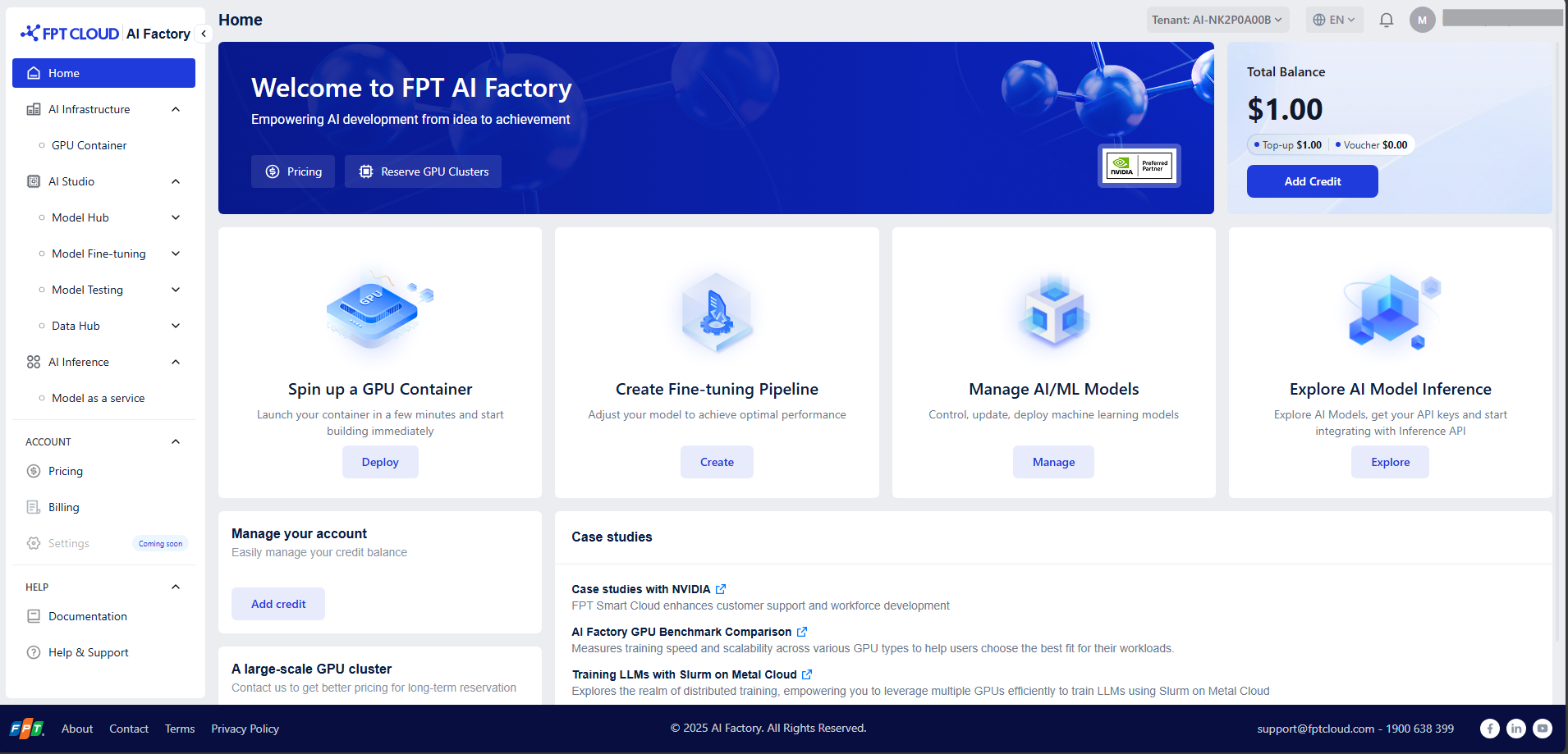](https://fptcloud.com/wp-content/uploads/2025/07/Screenshot-2025-07-04-175942.png)
## Step-by-step
After logging in to the FPT AI Factory portal at ai.fptcloud.com, follow the instructions below:
### Step 1: Add credit to account
1. Navigate to section ACCOUNT and click Billing
2. Click Add Credit button and enter an amount and payment information to complete.
Or, you have a voucher from FPT, apply your valid code in Add Voucher section to redeem credits
### Step 2: Create a container
1. Select GPU Container in the Side menu.
2. Click button **Create New GPU Container** and configure the Container deployment.
3. Follow the detailed guide [here](/fpt-gpu-cloud/gpu-container/tutorials/how-to-create-a-container).
### Step 3: Connect to container
1. In the Container list page, click container name to access container details screen.
2. Depends on your configurations in Access container section, choose one of the methods to connect: HTTP Endpoint, Connect SSH via Terminal
3. Follow the detailed guide [here](/fpt-gpu-cloud/gpu-container/tutorials/how-to-access-to-a-container)
### Step 4: Stop the container
To avoid incurring unnecessary charges, make sure to:
1. Return to the list container page.
2. Click the Stop button in the Actions column to stop your container.
3. Confirm by clicking "Confirm".
To delete your container permanently, follow the detailed guide [here](/fpt-gpu-cloud/gpu-container/tutorials/how-to-manage-container#stop-container).
# Tutorials
{% embed url="" %}
# How to Create a container?
#### Using GUI
Notice: Each tenant can only have a maximum of 10 containers. If you have reached this limit, please delete unused container to create a new one.
1. Select GPU Container in the Side menu and click button “Create New Container”
2. Give your container a name using **Container Name** field.
3. Select a GPU Instance (we currently support NVIDIA GPU H100 and H200)
4. **Template**: Users can either choose to use built-in templates or use their own images. We highly recommend that our customers to use built-in templates for faster deployment.
**a. Built-in templates**: Click “Change Template” and choose the template.

**b. Custom template**: Bring your own template by using the feature “Custom Template”.
5. **Access container**
**a. Ports**
This feature significantly enhances the flexibility of your containerized applications, allowing a single container to serve diverse functionalities on different ports.
Both HTTP and TCP ports are supported, with a maximum of 10 ports per type for each container.
**b. SSH**
Add SSH keys to enable remote access to your container. **Each container** **supports a maximum of 10 SSH keys**. These keys will be injected into the container at runtime, allowing you to SSH into the container using any of the provided keys.
*Notice: Currently, v1.1.2 GPU Container only Ubuntu, Pytorch, CUDA, Tensorflow template already includes SSH configuration. If you want to connect via SSH in other templates, please install OpenSSH-server before using.*
To add an SSH key, please follow the instructions:
1. Ensure you have an SSH key pair generated on your local machine. If you haven’t done this, you can generate one using this command on your local terminal:
`ssh-keygen -t ed25519 -C [YOUR_EMAIL@DOMAIN.COM](mailto:YOUR_EMAIL@DOMAIN.COM)`
2. To retrieve your public SSH key, run this command:
`cat ~/.ssh/id_ed25519.pub`
This will output something similar to this:
`ssh-ed25519 AAAAC4NzaC1lZDI1JTE5AAAAIGP+L8hnjIcBqUb8NRrDiC32FuJBvRA0m8jLShzgq6BQ YOUR_EMAIL@DOMAIN.COM`
3. Copy and paste the output into the SSH Public Keys field when you create the container.

6. **Advanced Settings** (**Optional**)
**a. Persistent Disk**: specify the amount of storage that users need to store training weights, models, etc. Read more about Storage [here](/fpt-gpu-cloud/gpu-container/tutorials#storage)
**b. Environment Variables:** key-value pairs injected into the container at runtime.
**c. Startup Command:** command and arguments to run at the start of container
7. Click “**Create New Container**” to create and start your container.
8. In case your balance is not enough to create a new container (lower cost of using the container for 1 hour), please follow these instructions to add credit to your account here[^1]
#### Importing YAML file
For quick deployment, or when you already have a configuration file prepared, use this feature to create a container rather than configuring it through the user interface.
**Step 1: Open Import Configuration modal**
1. Navigate to GPU Container from the side menu.
2. Click Import Configuration located on the top right of the container list page.

**Step 2: Provide configuration file in YAML format**
You can import the configuration in two ways:
* Paste YAML directly into the YAML editor.
* Upload a YAML file by clicking the Upload file button. Currently, GPU Container supports YAML files only.
A sample YAML template can be downloaded by clicking **Download template**.

| **Field** | **Data type** | **Sample data** | **Description** |
| ---------------------- | ------------- | ----------------------- | -------------------------------------------------------------------------------------------------------------------------------------------------------------------------------------------------------------------------------------------------------------------------------------------------------------- |
| name | string | my-container | Name of your container. Must be unique per tenant |
| instance\_type | string | GPU-H100-1 | Vietnam site supports 1xH100 -> 8xH100; Japan site supports 1xH200 -> 8xH200 |
| **image\_setting** | | | Since a container can only have 1 image, please provide either **template\_name** or **image\_url + image\_tag** |
| template\_name | string | Jupyter Notebook | Built-in template name. Provides this in case you want to use built-in template provided by FPT. Please input an exact name in the list: Jupyter Notebook, Code Server, vllm-openai, vllm-openai-v0.10.1, ollama, ollama-openwebui, Ubuntu 24.04, Tensorflow 2.19.0, Nvidia Cuda 12.9.1, NVIDIA Pytorch 25.03. |
| image\_url | string | registry/myimage:latest | (Optional) Custom image URL. Leave blank if using the built-in template. |
| image\_tag | string | v1.0 | (Optional) Tag for custom image. |
| image\_user | string | admin | (Optional) Username for private image registry. |
| image\_password | string | password123 | (Optional) Password for private image registry |
| **access\_container** | | | |
| tcp\_ports | list\[int] | \[22, 33] | TCP ports exposed by the container |
| http\_ports | list\[int] | \[8888, 6006] | HTTP ports exposed by the container |
| ssh\_keys | | | Provide each pair of name-key SSH keys. Allow a maximum of 10 keys |
| name | string | key01 | Name of the SSH key |
| key | string | "ssh-rsa AAAAB3..." | SSH public key |
| **advanced\_settings** | | | |
| persistent\_disk | | | |
| mount\_capacity | int (GB) | 20 | Amount of persistent storage to attach. |
| mount\_path | string | /workspace | Path where persistent disk will be mounted inside the container. |
| environment\_variables | | | |
| key | string | USERNAME | Environment variables injected at runtime. |
| value | string | admin | |
| startup\_commands | | | |
| cmds | list\[string] | | Startup commands (optional). |
| args | list\[string] | | Startup command arguments (optional). |
**Step 3: Review Configuration**
**Notice:** The button “Review" will only be enabled when all the validations within the YAML editor have passed.
Click **Review** to continue. On this screen, you can:
* Verify container configuration, including template, GPU, CPU, RAM, and disk allocation.
* Check the pricing summary to view the estimated hourly cost.

**Step 4: Create Container**
Once confirmed, click **Create Container** to start deployment. The system will automatically create and launch your container based on the provided configuration file.
#### Export Container Configuration
For later reuse, the Export Configuration feature allows you to save a container’s configuration and download it into a YAML file.
1. From the List Containers screen, click the Action (3-dot) menu and select Export Configuration.

1. Alternatively, open the Container Details page and click Export Configuration.

A YAML file will be automatically downloaded with the name format: **container-name.yaml**
[^1]:
# How to Access to a container?
You can connect to your GPU Container using a few different methods, depending on your specific needs, preferences, and the template used to create the container.
1. [HTTP Service](https://ai-docs.fptcloud.com/~/revisions/d0RttJwM2X9AdNT4NYCf/ai-infrastructure/gpu-container/tutorials/how-to-connect-to-a-container/http-service)
2. [TCP Ports](https://ai-docs.fptcloud.com/~/revisions/nhjbUQwZ5R8UPjWKDbKz/ai-infrastructure/gpu-container/tutorials/how-to-connect-to-a-container/tcp-ports)
3. [SSH Terminal Connection ](https://ai-docs.fptcloud.com/~/revisions/nhjbUQwZ5R8UPjWKDbKz/ai-infrastructure/gpu-container/tutorials/how-to-connect-to-a-container/ssh-terminal-connection)
# HTTP Service
#### How to connect via HTTP?
1. Once the container is running, navigate to Container Details Page.
2. Find Access container Section, open HTTP Endpoint.
3. Follow the guide that matches your template.
Template
Pre-condition
Next steps
Jupyter, Code Server
None
Open the endpoint in your browser
Use the Username and Password fields in the Environment Variables section of the Container Details page to access your container
Ollama WebUI
None
Open the endpoint in your browser
Create a new Open WebUI account or use your existing account.
[^1]: Append **/v1/models** to your endpoint, then provide your API\_TOKEN in the Authorization. If you're using the vLLM template, also include HUGGING\_FACE\_HUB\_TOKEN in the request parameters to test your container.
[^2]: Hugging Face Token in Environment Variable section is required when using Ollama template. If you do not have Hugging Face Token yet, please follow this guide [User access tokens](https://huggingface.co/docs/hub/en/security-tokens).
# TCP Ports
To access your instance via public endpoint, you will need to add TCP ports to the container configuration. When your container is created, you will receive a public domain and an external public port mapping to access your service. An external public port will be randomly selected from the range 30000-40000.
The format will be DOMAIN:EXTERNAL\_PORT -> INTERNAL\_PORT. For example:
tcp-endpoint-stg.serverless.fptcloud.com:34771 → :22
# SSH Terminal
You can add up to 10 SSH keys to enable remote access. These keys will be automatically injected into the container at runtime, allowing you to SSH into the container using any of them.
#### Pre-configured SSH Templates
SSH is already set up and ready to use on the following templates:
* Code Server
* Ubuntu 24.04
* TensorFlow 2.19.0
* Nvidia CUDA 12.9.1
* Nvidia PyTorch 25.03
{% hint style="info" %}
If you want to connect SSH in other templates, please install OpenSSH-server before using.
{% endhint %}
#### How to add SSH key?
1. Ensure you have an SSH key pair generated on your local machine. If you haven’t done this, you can generate one using this command on your local terminal:
```
ssh-keygen -t ed25519 -C YOUR_EMAIL@DOMAIN.COM
```
2. To retrieve your public SSH key, run this command:
```
cat ~/.ssh/id_ed25519.pub
```
This will output something similar to this:
```
ssh-ed25519 AAAAC4NzaC1lZDI1JTE5AAAAIGP+L8hnjIcBqUb8NRrDiC32FuJBvRA0m8jLShzgq6BQ YOUR_EMAIL@DOMAIN.COM
```
3\. Copy and paste the output into the SSH Public Keys field:
4. To get the SSH command for your container, navigate to the Container details page. Copy the command listed under SSH command.
It should look something like this:
```
ssh root@tcp-endpoint-stg.serverless.fptcloud.com -p 34771 ~/.ssh/id_e25595
```
5. Run the copied command in your local terminal to connect to your container.
# How to Manage container?
#### Start Container
1. Open the List Containers.
2. Find the GPU Container you want to start and click the 3-dot icon.
3. Select “Start” action.
#### Edit Container
[Notice: Saving your changes will restart the container. Please note that all data on the temporary disk will be permanently lost.](#user-content-fn-1)[^1]
1. From the List Containers, select the container you want to edit and access "Container Details" screen.
2. Click the Edit icon of the section you want to modify. You can now edit the 'Access container' section (including Ports and SSH) and the 'Advanced settings' section (including Persistent Disk, Environment Variables, and Startup Commands).
3. Confirm by clicking “Save”.
#### Stop Container
Warning: You will be charged for idle GPU containers even if they are stopped. If you don’t need to retain your container, you should terminate it completely.
1. Open the List Containers
2. Find the GPU Container you want to stop and click the 3-dot icon
3. Select “Stop” action
4. Confirm by clicking “Confirm”
#### Delete Container
Danger: Deleting a container permanently deletes all data in temporary storage and persistent storage. Be sure you’ve saved any data you want to access again.
1. Open the List Containers.
2. Find the GPU Container you want to delete and click the 3-dot icon.
3. Select “Delete” action.
4. Confirm by entering “delete” in the text field and clicking “Confirm”.
[^1]:
# How to Monitor container?
GPU Container provides **container logs** and **metrics** to help you monitor and troubleshoot your workloads. To view your logs and metrics, open the Details Container screen, open the Logs or Monitoring tab. This gives you container logs and metrics monitoring, making it easy to diagnose issues or monitor your container’s activity.
#### Container Logs
Container logs include all application logs. Note that logs are only kept for 14 days, and timestamps are shown in the UTC timezone.

1. Download: Download logs from the last 14 days of your container.
2. Search: Enter a keyword to search within the log content.
3. Time Filter: Filter logs by specific time ranges.
4. Refresh: Interval at which the container logs are automatically updated.
#### Metric Monitoring
Monitoring metrics are collected to track the performance, availability, and resource usage of containerized services, helping detect issues and optimize operations. Note that metric data is retained for 14 days.
There are 4 metric groups:
* **Utilization metrics**: Monitor CPU, memory, and GPU usage to assess system performance and resource efficiency.
* **Disk metrics**: Track disk read/write speed, and latency to detect storage issues or bottlenecks.
* **Network metric**: Measure network traffic, latency, and errors to identify connectivity problems and ensure service reliability.
* **Temperature and Power metrics**: Monitor hardware temperature and power consumption to prevent overheating and maintain hardware health.

1. Time Filter: Filter metrics by specific time ranges.
2. Refresh: Interval at which the container metrics are automatically updated.
# How to Manage template?
Templates are used to launch images as containers and define the required container disk size, volume, volume paths, and ports needed. You can also define environment variables and startup commands within the template.
#### Built-in Templates
These templates are created and maintained by FPT AI Factory. We now offer 6 built-in templates:
1. **Jupyter Notebook**
* Intended Use: This template provides Jupyter Notebook to adopt remote development for AI/Data Scientists without local hardware limitations.
* Environment Variables
Some more useful environment variables are provided for container customization.
| Variable | Type | Default | Description |
| -------- | ------ | ------- | -------------------------------------------------------------------------------- |
| USERNAME | string | admin | Username to access Jupyter Notebook |
| PASSWORD | string | |
Password to access Jupyter Notebook
Generate by system
|
* Port
| Type | Port |
| ---- | ---- |
| HTTP | 8000 |
| TCP | 22 |
2. **Ollama WebUI**
* Intended Use: This template supports running various large language model (LLM) programs, including Ollama and APIs compatible with OpenAI, making it easy for users to customize based on workflow.
* Port:
| Type | Port |
| ---- | ---- |
| HTTP | 8080 |
| TCP | 22 |
3. **Ollama**
* Intended Use: This template enables high-throughput inference using GPU resources with a state-of-the-art engine.
* Environment Variables
Some more useful environment variables are provided for container customization.
| Variable | Type | Default | Description |
| ---------- | ------ | ------- | ------------------------------------------------------------------------------------- |
| API\_TOKEN | string | |
Auto-authenticate with external services
Generate by system
|
* Port:
| HTTP | 8000 |
| ---- | ---- |
4. **vLLM**
* Intended Use: This vLLM container image is built and maintained by AI Factory. This template enables high-throughput model inference using GPU resources with a state-of-the-art engine.
* Environment Variables
Some more useful environment variables are provided for container customization.
| Variable | Type | Default | Description |
| ------------------------- | ------ | ------- | ----------------------------------- |
| HUGGING\_FACE\_HUB\_TOKEN | string | | Your Hugging Face User Access Token |
* Port:
| Type | Port |
| ---- | ---- |
| HTTP | 8000 |
5. **Code Server**
* Intended Use: This template offers cloud-based VS Code with GPU to train, test, and debug AI models remotely with full IDE capabilities.
* Environment Variables
Some more useful environment variables are provided for container customization.
| **Variable** | **Type** | **Default** | **Description** |
| ------------------ | -------- | --------------------- | ------------------------------------------------- |
| PUID | int | 0 | UserID |
| PGID | int | 0 | GroupID |
| TZ | string | Etc/UTC | Your timezone |
| PROXY\_DOMAIN | string | code-server.my.domain | The domain will be proxied for subdomain proxying |
| DEFAULT\_WORKSPACE | string | / | Default folder opened when accessing code-server |
| PASSWORD | string | | Generate by system |
* Port:
| Type | Port |
| ---- | ---- |
| HTTP | 8443 |
| TCP | 22 |
6. **Ubuntu**
| Type | Port |
| ---- | ---- |
| TCP | 22 |
* Intended Use: This is a minimal Ubuntu CLI virtual machine with several useful additions to improve your user experience. While the root account is available as usual, we have created a normal system user for your convenience.
* Development tools pre-installed: SSH access.
#### Custom Templates
You can use your own **Docker image** by clicking **Custom Template** and overriding your own image:tag. If your image is from a private Docker repository, make sure to provide your **username and password** for authentication.

# How to Manage storage?
#### Persistent Disk
GPU Container provides High-Performance Storage (HPS) remaining for the duration of a container’s life. It functions similarly to a hard disk, allowing you to store data that needs to be retained even if the container is stopped.
Key characteristics:
* Available until the container is deleted permanently.
* Prevent data loss by storing data, models, or files that need to be preserved across container restarts or reconfigurations.
#### Temporary Disk
Temporary disk (NVMe) is a type of storage that provides temporary storage for a container. Any data stored on the temporary disk will be lost when the container is stopped or deleted so make sure to back up important data before shutting down your container.
#### Storage type comparision
| | **Temporary Disk** | **Persistent Disk** |
| -------------------- | ----------------------------------------------- | ---------------------------------------------- |
| **Data persistence** | Lost on stop/ restart | Retained until container deletion |
| **Lifecycle** | Tied directly to the container’s active session | Tied to the container’s lease period |
| **Performance** | Fastest (locally attached) | Reliable, generally slower than temporary disk |
| **Capacity** | Fixed according to the selected GPU instance | Selectable at creation |
| **Cost** | FREE | Refer to ai.fptcloud.com/pricing |
| **Best for** | Temporary session data, cache | Persistent application data, models, datasets |
# How to Whitelist IP?
**The Whitelist IP** feature enhances your container's security by restricting access to only authorized sources.
* **Default State**: All IP addresses are allowed to access the Container.
* **After Configuration**: Access is strictly limited to the IP addresses defined in your whitelist.
{% hint style="success" %}
**Prerequisite**: This feature is only available after a Container has been successfully created and is in "Running" status.
{% endhint %}
#### Access the Feature
1. You need to [Create a container](https://ai-docs.fptcloud.com/~/revisions/MN07vkRkyAKKaDfqwwSf/fpt-gpu-cloud/gpu-container/tutorials/how-to-create-a-container) before using this feature.
2. Navigate to the **Container View** screen and select the specific Container you wish to secure.
3. Click on the **Whitelist IP tab** from the navigation menu.
#### Add a New Whitelist IP Rule
1. Click the **\[+ Add Rule]** button. A new entry row will appear in the list.
2. Configure the Rule Details:
Field
Description
Format / Requirement
Type
Choose the protocol for the rule.
TCP or HTTP
Port
Ports are automatically populated based on your Container's access settings.
You can manually remove specific ports to limit the rule's scope.
Source
Define the specific IP addresses or ranges allowed to access.
• Single IPv4: 192.168.1.1
• CIDR Range: 192.168.1.0/24
• Bulk: Use commas for multiple IPs.
Description (Optional)
Add a short note to identify the purpose of this rule .
Alphanumeric, max 100 characters.
3. Click **Save** to deploy the configuration.
#### View Whitelist IP
Field
Description
Examples
Protocol
Shows the assigned communication protocol for the rule.
TCP, HTTP
Port
Displays the specific service ports protected by the rule.
22, 80, 443, 8080
Source (Inbound only)
Lists the authorized IP addresses or network ranges allowed to access the container.
Single IP (1.2.3.4) or CIDR (1.2.3.0/24)
Description (Optional)
Displays custom labels used to quickly identify the purpose of the rule.
"Dev Team", "Office VPN", "Customer A"
**Filter**: The top navigation bar provides dynamic filters to help you locate specific rules quickly, especially when managing large environments.
* **By Protocol**: Click the Protocol dropdown to isolate rules by their communication type.
* **By Port**: Use the Port filter to find all rules associated with a specific service port.
* **By Source**: Use the Source search box to filter the list by a specific IP address or network range.
#### Edit Whitelist IP
You can update any field of an existing rule without having to delete and recreate it.
1. Click **Edit** button
2. Edit Rules
3. Click the **Save** button (usually located at the bottom of the table) to push your updates live.
#### Delete Whitelist IP
If a rule is no longer needed (e.g., a project has ended or a consultant no longer needs access), you can remove it permanently.
{% hint style="danger" %}
*Once a rule is deleted, the blocked IP addresses will immediately lose access to the specified ports.*
{% endhint %}
1. Click **Edit** button
2. Locate the rule you wish to remove in the Whitelist table.
3. Navigate to the Action column on the far right and click the **Trash Can icon** (Red) associated with that specific row.
4. Click the **Save** button (usually located at the bottom of the table) to push your updates live.
# Use cases
---
[Next Page](/llms-full.txt/1)


